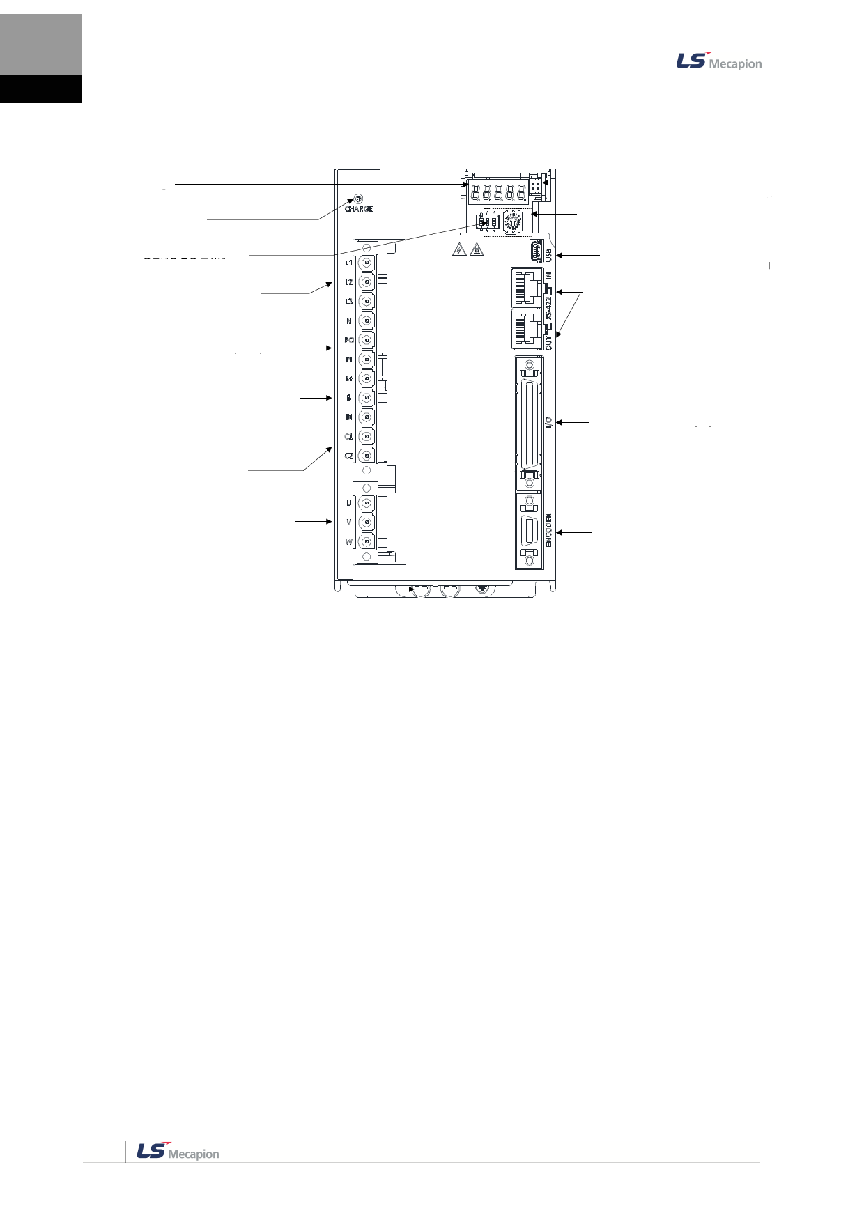
1. Product Composition
2kW, 3.5kW
Display Window
Shows the status and alarms of the drive
Charge Lamp
The lamp lights up when the main circuit is
Terminating Resistance Setting
When the switch is on, the drive’s internal
terminating resistance (120Ω) is used
Main Power Connectors (L1, L2, L3)
Terminals for power supply into the main circuit
DC Reactor Connection Connector (PO, PI)
DC reactor connection terminals for inhibition of high-
frequency wave from the power unit
Recovery Resistance Connection Connector
(B+, B, BI)
Connection terminals for external recovery resistor
– Basic attachment: B, BI termination
– External resistor attached: attached to B+, B
terminal
Control Power Terminal (C1, C2)
Terminal for control power input
Servo Motor Connection Terminal (U, V, W)
Connection terminal for the motor’s main
circuit cable (power cable)
Ground Terminal
Earthing terminal to prevent electrocution
Analog Monitor Connector
Connector for monitoring of analog
output signal
Node Address Switch
This switch sets the drive’s node address.
You can set node address at from 0 to 31
USB Connector (USB, Mini B Type)
Communication connector with Drive
CM programs (PC programs)
RS-422 Communication Connector
(In/Out)
RS-422 Communication Connector
Input/Ouput Signal Connector (I/O)
Connector for sequence input/output
signal
Encoder Connector (ENCODER)
Connector with encoder mounted on
the servo drivei
1-10

