
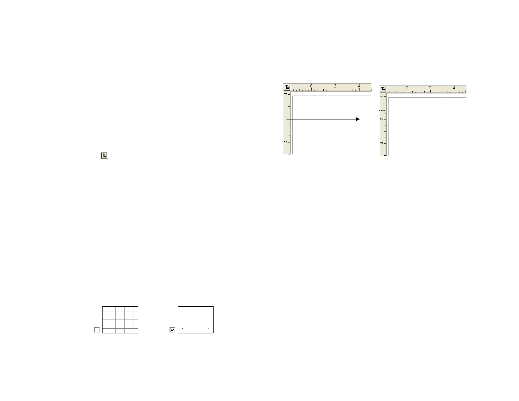
Click and drag the Origin icon
The new Origin
You can also adjust the origin’s position by using the Ruler and Grid
Settings dialog box.
Displaying the Ruler and Grid Settings
Do one of the following:
• Double-click the Origin icon in the upper left corner of the
design area.
• From the View menu, select Ruler and Grid.
The Ruler & Grid dialog box consists of Ruler and Grid tabs.
On the Ruler tab, adjust the following parameters:
Origin
Enter the X, Y coordinates of the new origin.
Orientation
Click one of these buttons to change the orientation of the
coordinates in the X, Y rulers.
Units
Select the unit system that will be used for length values from
this list.
On the Grid tab, adjust the following parameters:
Spacing
Snap to grid
Show grids as
dots
Horizontal and vertical space between adjacent dots.
Check this option to snap the objects to the grid while moving
or resizing them.
Check to display grids as dots at the intersection points instead
of solid lines.
Guides
Guides allow you to visually align design elements on your document.
© 2006 SA International
To show or hide the guides, from the View menu, point to Show and select
Show Guides.
Creating a Horizontal or Vertical Guide Line
• Click and drag one point on the ruler. Horizontal or vertical
guide lines are created depending on which ruler you drag from.
Click and drag
Click and drag a point in the ruler
A new vertical guide is created
Converting Objects to Guides
1 Select objects.
2 From the Arrange menu, point to Guides and click Make
Guide.
3 Select Release Guide in the same menu to convert guides back
to original objects.
Or
• In DesignEditor, drag objects from generic layer to Guide Layer.
See “DesignEditor - Layers Tab” on page 29 for more
information.
Creating a Diagonal Guide
1 Create a horizontal or vertical guide.
2 Rotate the horizontal or vertical guides using DesignCentral -
Rotate tab.
Hold Shift to constrain the line angle to increments of 45 degrees.
7
 Flexi Help")
 Flexi Help")
 Flexi Help")
 Flexi Help")
 Flexi Help")
 Flexi Help")
 Flexi Help")
 Flexi Help")