Method 2:
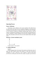
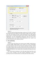
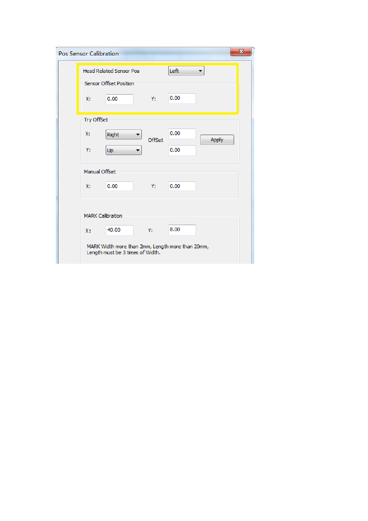
If the laser head has infrared beam design, the direct use of X and Y to measure
the deviation between the midpoint of the ruler and the red light of the sensor values,
at the same time through the relative position determination sensor light midpoint
position relative to red mark point, directly select the “left-top / right-top/ left-bottom
/right-bottom”; and the corresponding measurement value to fill out the"
corresponding position sensor offset, and the implementation of the "confirm" ,and
then close the position sensor calibration interface.
2:Fine positioning
Method 1:
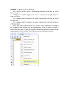
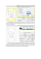
On the left side of the drawing tools selected location "MARK" standard (below)
", then the MARK standard format for any position, and set the corresponding
processing parameters in the laser processing layer management interface, and then
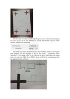
use a piece of paper stuck on a piece of hard wood as the test object, put the
corresponding position in the format, and then click start processing, the software will
download the MARK file to the controller after the automatic processing and accurate
calibration;
Note: under normal circumstances on the white paper burned black traces need
11%-13% power, according to the actual situation. Recalibration of the sensor
according to the color of the burn marks to accurately detect the relative position.

