
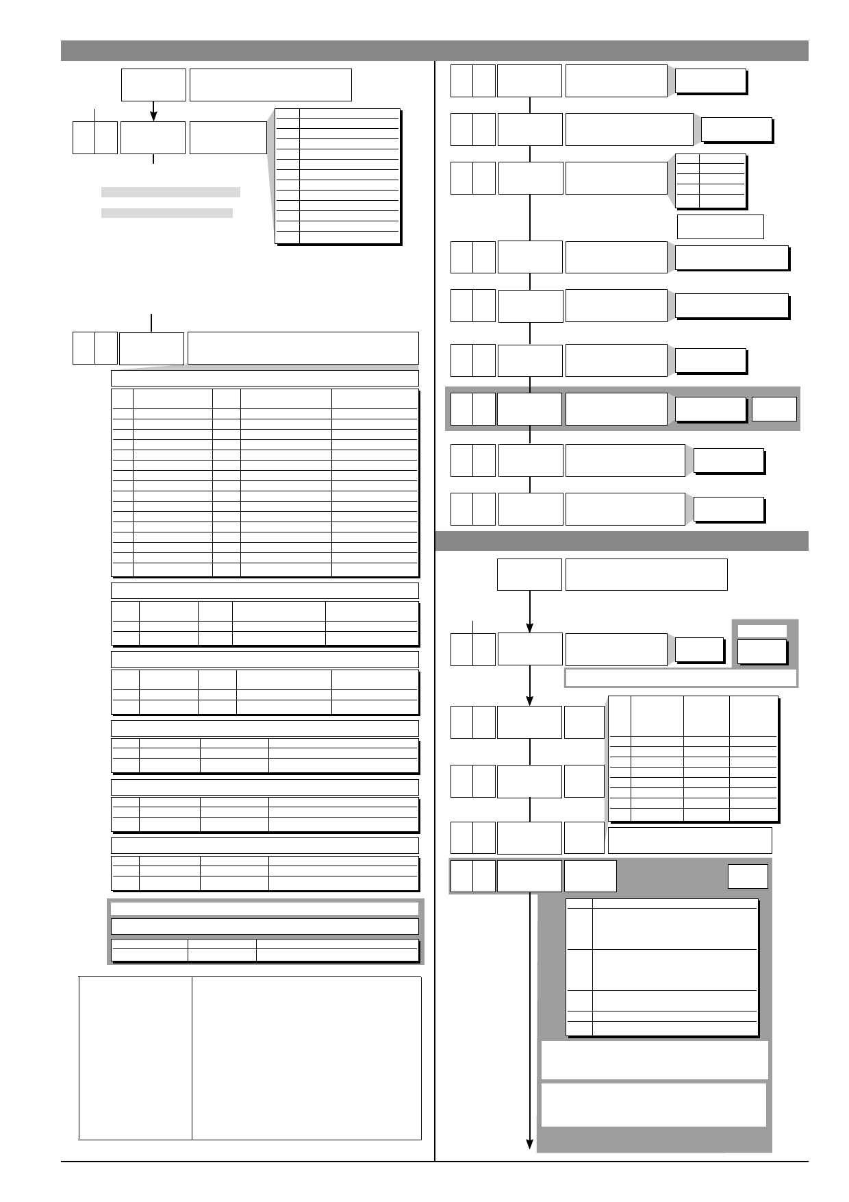
InP
Input settings
Configurat.
Default Custom
22 (tr
Type of control
[0...91]
+16 disable parameters
CFG: rst, PrE, SoF, Lbt, Lbp, FAP,
HY.2, HY.3 (only for model 400)
InP: FLt, FLd, oFS, LoL, HIL
Out: ALn, A2t, A3t (only for model 400), rEL
FLt, FLd, oFS stay at set value.
ALn is forced to 1 (only for mod. 400)
All other parameters are considered 0.
CtrL Type of control
0 P hot
1 P cold
2 P hot / cold
3 PI hot
4 PI cold
5 PI hot / cold
6 PID hot
7 PID cold
8 PID hot / cold
9 ON-OFF hot
10 ON-OFF cold
11 ON-OFF hot / cold
Default: derived action sample time = 1 sec
+32: derived action sample time = 8sec
+64: derived action sample time = 240msec with derived action filter assigned
to Flt parameter (time filter)
• InP
0.1
0.5
0
0
1000
FLt
Digital filter
on main input
0,0 ... 20,0 sec
FLd
dP.S
Lo.S
Digital filter on display of
process variable; acts as
hysteresis
Decimal point position for
main input scale
dP.S
0
1
2
3
0 ... 9,9
scale points
Format
xxxx
xxx.x
xx.xx (*)
x.xxx (*)
(*) not available for
TC, RTD, PTC scales
Minimum limit of main
input scale
min…max scale of input
selected in tyP
Maximum limit of main
XI.s
input scale
min…max scale of input
selected in tyP
0 tyP
Type of probe, signal and scale of main input
SENSOR: TC
(CAL = 1)
tYP Type of probe
Scale
(C/F)
0 J (Fe-CuNi)
C
1 J (Fe-CuNi)
F
2 K (NiCr-Ni)
C
3 K (NiCr-Ni)
F
4 R (Pt13Rh - Pt)
C
5 R (Pt13Rh - Pt)
F
6 S (Pt10Rh - Pt)
C
7 S (Pt10Rh - Pt)
F
8 T (Cu-CuNi)
C
9 T (Cu-CuNi)
F
10 B (Pt30Rh - Pt6Rh) C
11 B (Pt30Rh - Pt6Rh) F
12 E (NiCr-CuNi)
C
13 E (NiCr-CuNi)
F
14 N (NiCrSi-NiSi)
C
15 N (NiCrSi-NiSi)
F
Max. scale range
without decimal point
0 / 1000
32 / 1832
0 / 1300
32 / 2372
0 / 1750
32 / 3182
0 / 1750
32 / 3182
-200 / 400
-328 / 752
44 / 1800
111 / 3272
-100 / 750
-148 / 1382
0 / 1300
32 / 2372
Max. scale range
with decimal point
0,0 / 999,9
32,0 / 999,9
0,0 / 999,9
32,0 / 999,9
0,0 / 999,9
32,0 / 999,9
0,0 / 999,9
32,0 / 999,9
-199,9 / 400,0
-199,9 / 752,0
44,0 / 999,9
111,0 / 999,9
-100,0 / 750,0
-148,0 / 999,9
0,0 / 999,9
32,0 / 999,9
SENSOR: RTD 3 wires (CAL = 2)
tYP Type of probe
16 PT100
17 PT100
Scale
(C/F)
C
F
Max. scale range
without decimal point
-200 / 850
-328 / 1562
Max. scale range
with decimal point
-199,9 / 850,0
-199,9 / 999,9
SENSOR PTC
tYP Type of probe
18 PTC
19 PTC
(CAL = 3)
Scale
(C/F)
C
F
Max. scale range
without decimal point
-55 / 120
-67 / 248
Max. scale range
with decimal point
-55.0 / 120.0
-67.0 / 248.0
SENSOR: VOLTAGE 60Mv
tYP Signal type
20 0...60mV
21 12...60mV
Scale
linear
linear
(CAL = 4)
Max. scale range
-1999 / 9999
-1999 / 9999
SENSOR: CURRENT 20mA or TRANSMITTER
(CAL = 5)
tYP Signal type
22 0...20mA
23 4...20mA
Scale
linear
linear
Max. scale range
-1999 / 9999
-1999 / 9999
SENSOR: VOLTAGE 10V or TRANSMITTER
(CAL = 6)
tYP Signal type
24 0...10V
25 2...10V
Scale
linear
linear
Max. scale range
-1999 / 9999
-1999 / 9999
With mod. 401, set CAL=7 to calibrate the current transformer input
SENSOR CT: CURRENT 50mAac
(CAL = 7)
Signal type
0 ... 50mAac
Scale
linear
Max. scale range
0 ... 99,9
Max. non-linearity error
for thermocouples (TC),
resistors (PT100) and
thermistors (PTC).
The error is calculated
as deviation from
theoretical value
and is expressed as
percentage of full scale
(in °C
S, R range 0...1750°C; error < 0.2% f.s. (t > 300°C) / for
other range; error < 0.5% f.s.
T error < 0.2% f.s. (t > -150°C)
B range 44...1800°C; error < 0.5% f.s. (t > 300°C) /
range 44,0...999,9; error < 1% f.s. (t > 300°C)
Tc: J, K, E, N,
error < 0,2% f.s.
PTC
error < 0,2% f.s.
PT100 scale -200...850°C
Precision better than 0,2% f.s. at 25°C
0
oFS
Main input offset
correction
-999 ... 999
scale points
99.9
xI.A Max. current transformer
input scale
0,0...99,9
mod. 401
0
Lo.L Lower limit for local setpoint
and absolute alarms
Lo.S ... Hi.S
1000
xI.L Upper limit for local setpoint
and absolute alarms
Lo.S ... Hi.S
• Out
Out
Output settings
Configurat.
Default Custom
1 AL.n
0 AI.t
0 A2.t
0 A3.t
Number of alarms
mod. 400
0 ... 3
mod. 401
0 ... 6
4, 5, 6 to select HB alarm as alternative to alarm 3
Alarm
type 1
Alarm
type 2
Alarm
type 3
AL.x
0
1
2
3
4
5
6
7
Direct
(maximum)
Inverse
(minimum)
direct
inverse
direct
inverse
direct
inverse
direct
inverse
Absolute
Relative
to active
setpoint
absolute
absolute
relativo
relativo
absolute
absolute
relativo
relativo
Normal
Symmetrical
(window)
normal
normal
normal
normal
symmetrical
symmetrical
symmetrical
symmetrical
+ 8 to disable on power-up until first alarm
0
xb.F Function of
HB alarm
mod. 401
Hb_F Description
0 Relay, logic output: alarm active
with load current value below
limit set in ON time
of control output
1 Relay, logic output: alarm active
with load current value above
limit set in OFF time
of control output
2 Alarm active if one of functions 0 and 1
is active (OR logic for functions 0 and 1) (*)
3 Alarm HB continuous heating (**)
7 Alarm HB continuous cooling (**)
+0 assigned to OUT1 (only for Hb_F = 0, 1, 2)
+4 assigned to OUT2 (only for Hb_F = 0, 1, 2)
+16 alarm HB reverse
(*) minimum limit is set = 12.5% of current transformer f.s.
(**) As type 0 without reference to cycle time .
81503D_MHW_400-401_12-2010_ENG
11
 400 401 Single Display Temperature Controller With Universal Input Installation and Operation Manual")
 400 401 Single Display Temperature Controller With Universal Input Installation and Operation Manual")
 400 401 Single Display Temperature Controller With Universal Input Installation and Operation Manual")
 400 401 Single Display Temperature Controller With Universal Input Installation and Operation Manual")
 400 401 Single Display Temperature Controller With Universal Input Installation and Operation Manual")
 400 401 Single Display Temperature Controller With Universal Input Installation and Operation Manual")
 400 401 Single Display Temperature Controller With Universal Input Installation and Operation Manual")
 400 401 Single Display Temperature Controller With Universal Input Installation and Operation Manual")
 400 401 Single Display Temperature Controller With Universal Input Installation and Operation Manual")
 400 401 Single Display Temperature Controller With Universal Input Installation and Operation Manual")
 400 401 Single Display Temperature Controller With Universal Input Installation and Operation Manual")
 400 401 Single Display Temperature Controller With Universal Input Installation and Operation Manual")
 400 401 Single Display Temperature Controller With Universal Input Installation and Operation Manual")
 400 401 Single Display Temperature Controller With Universal Input Installation and Operation Manual")
 400 401 Single Display Temperature Controller With Universal Input Installation and Operation Manual")
 400 401 Single Display Temperature Controller With Universal Input Installation and Operation Manual")
 400 401 Single Display Temperature Controller With Universal Input Installation and Operation Manual")
 400 401 Single Display Temperature Controller With Universal Input Installation and Operation Manual")
 400 401 Single Display Temperature Controller With Universal Input Installation and Operation Manual")
 400 401 Single Display Temperature Controller With Universal Input Installation and Operation Manual")
 400 401 Single Display Temperature Controller With Universal Input Installation and Operation Manual")