5/14/2018
DZB Series
Chapter 3 Mechanical and Electrical Installation
DZB Series
Fuling Inve r te r Use r Ma nua l - slide pdf.c om
3.2 Electrical Installation
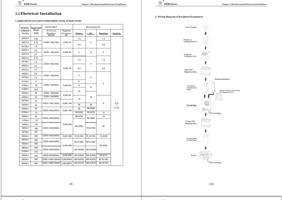
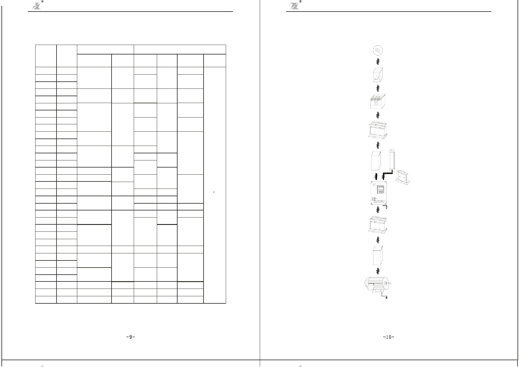
1.Applicable devices and recommendable wiring of main circuit:
2. Wiring Diagram of Peripheral Equipment
MODEL Applicable
DZB300 Motor
Series (KW)
0005L2
0.55
INPUT(RST)
Air Circuit
Breakers
MCCB
Magnetic
Contactor
MC
Wire Size(mm2)
TPeromwienral
1.5
R eDaCc t o r
BTreermakininagl
1.5
0007L2
0.75
DZ20-100(16A) CJ20-16
4
2.5
2.5
0015L2
1.5
0022L2
2.2
DZ20-100(32A) CJ20-40
4
6
4
0037L2
3.7
0007L4
0015L4
0022L4
0.75
1.5
2.2
DZ20-100(16A)
1.5
1.5
4
0037L4
3.7
CJ20-16
2.5
2.5
0055L4
5.5
0075L4
7.5
DZ20-100(32A)
4
6
0110L4
11
6
4
0150L4
15
DZ20-100(50A) CJ20-40
8
8
0185L4
18.5
10
0220L4
22
DZ20-100(63A)
CJ20-63
0300L4
30
DZ20-100(80A)
16
16
0370L4
37
0450L4
DZ20-100(100A) CJ20-100
45
25
25
6
0550L4
55
35
DZ20-200(200A) CJ20-160
25*2(50)
0750L4
75
25*2(50) 35*2(70)
10
0930L4
1100L4
93
DZ20-400(250A)
110
35*2(70) 50*2(95)
16
1320L4
132
CJ20-250
50*2(95)
25
1600L4
160
DZ20-400(350A)
70*2(150)
1870L4
187
2000L4
2200L4
2500L4
2800L4
3150L4
200
DZ20-400(400A) CJ20-400 70 2(150) 70 2(150) 16 2(35)
*
*
*
220
DZ20-630(500A)
95*2(185) 95*2(185)
250
CJ20-630
25*2(50)
280
DZ20-630(600A)
120*2(240) 120*2(240)
315
4000L4
400
DZ20-800(800A) CJ20-800 150*2(300) 150*2(300) 35*2(70)
5000L4
6300L4
500 DZ20-1250(1000A) CJ20-500*2 185*2(370) 185*2(370) 50*2(100)
630 DZ20-1250(1250A) CJ20-630*2 185*2(370) 185*2(370) 50*2(100)
TCeormntirnoall
0. 5
0.75
Pow er Supply
Breaker or
Leakage Sw itch
M agnetic
Contactor( M C)
Input AC
Reactor(AC)
InputSide
Interference
Filter
Inverter
O utput AC
Reactor(AC)
O utput Side
N oise Filter
M otor
Chapter 3 Mechanical and Electrical Installation
Braking Resistor
Pow er-factor-im proving
D C Reactor(D C)
G rounding
G rounding
-9-
http://slide pdf.c om/re a de r/full/fuling-inve r te r-use r-ma nua l
-10-
8/54

