DZB0 Series
Chapter 5 Function Parameters List
DZB Series
Chapter 5 Function Parameters List
5/14/2018
Fuling Inve r te r Use r Ma nua l - slide pdf.c om
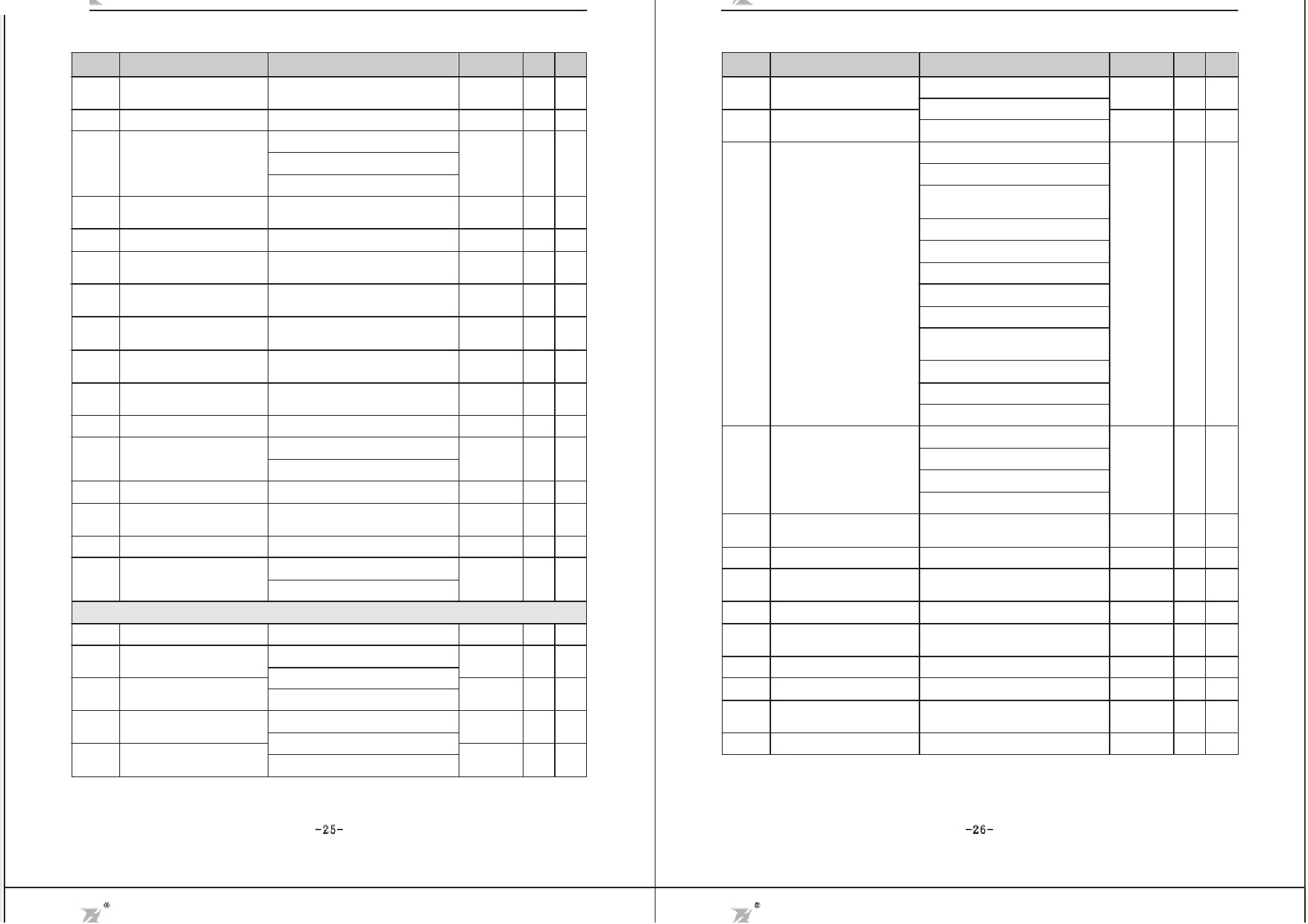
Function
Code
Name
F1.09
Mutual inductance of
motor stator/rotor
F1.10 No-load current
Self-learning of
F1.11 motor parameters
(Invalid for DZB200)
F1.12
Speed loop proportional
gain1
F1.13 Speed loop integral time1
F1.14
Switching low
point frequency
Setting Range
0. 1~6553. 5mH
0. 01~655. 35A
0:NO operat ion
1:complete tuning Self-learning
2:static tuning Self-learning
0~1 00
0. 01~10.00s
0. 00Hz~F1.1 7
Default
Value
Set by
model
Set by
model
Modifi Serial
cation No
※ 35 .
※ 36 .
0
● 37 .
30
0.50s
5. 0 0 Hz
※ 38 .
※ 39 .
※ 40.
Function
Code
F2.05
Name
S5 Terminal F unction
Selection
F2 .0 6
S6 Terminal F unction
Selection
F1.15 Sgapiene2d loop proportional
0~1 00
25
F1.16
Speed loop integral
time 2
F1.17
Switching high
point frequency
0. 01~10.00s
F1.14~F0. 04
1.0 0s
10 . 00 H z
F1.18
VC slip compensating
factor
F1.19 Upper torque limit setting
5 0 %~2 0 0%
100%
0.0~200.0%(inverter rated current) 150.0%
0:Linear V/F curve
F1.20 V/F curve setting
1:square torque V/F curve
0
F1.21 Torque boost
0. 0%:(auto) 0.1%~30 .0%
0
F1.22 Torque bo ost cut-off
0.0%~50.0% (relative to motor
rated frequency)
20.0%
F1.23 V/F slip compensation limit 0 . 0~2 0 0. 0%
100%
F1.24
Energy Conservation
Selection
0:No Operation
1:Energy Conservation
0
F2 Input and Output Terminal Function Parameters
F2.00 On-off signal filter times 1~10
5
F2.01
S1 Terminal Function
Selection
0:No Function
1
1:Forward
F2.02
S2 Terminal Function
Selection
2:Reverse
2
F2.03
S3 Terminal Function
Selection
3:three-wire control
4
4:Forward Jogging
F2.04
S4 Terminal Function
Selection
5:Reverse Jogging
7
※ 41.
※ 42.
※ 43.
※ 44.
※ 45.
● 46.
※ 47.
● 48 .
※ 49 .
** 50 .
※ 51.
● 52 .
● 53 .
● 54 .
● 55.
F2.07
Terminal control
mode
F2.08
F2.09
F2.10
F2.11
F2.12
F2.13
F2.14
F2.15
F2.16
UP/DOWN frequency
increment variable rate
VI lower limit
VI lower limit
corresponding setting
VI upper limit
VI upper limit
corresponding setting
VI input filtering time
CI lower limit
CI lower limit
corresponding setting
CIupper limit
Setting Range
6:Free run stop
7:Failure reset
8:External fault input
9:Frequency setting(UP)
10:Frequency setting(DOWN)
11:Frequency up/down setting
clear
12:Multi-Speed Terminal 1
13:Multi-Speed Terminal 2
14:Multi-Speed Terminal 3
Default
Value
12
Modifi Serial
cation No
● 56 .
13
● 57 .
15:ACCEL/DECEL Time selection
16:PID control pause
17:Traverse pause at current
frequency
18:Traverse reset
19:ACCEL/DECEL forbid
20~25: Res er ved
0:two-wire control 1
1:two-wire control 2
2:three-wire control 1
3:three-wire control 2
0
● 58.
0. 01~50. 00Hz /s
0.50Hz/s ※ 59.
0. 00V~10. 00V
- 100. 0%~100.0%
0. 00V~10. 00V
0.00V
0.0%
10.00V
※ 60 .
※ 61 .
※ 62.
- 100. 0%~100.0%
0. 00s~10. 00s
0. 00V~10. 00V
- 100. 0%~100.0%
0. 00V~10. 00V
100.0%
0.10s
0.0 0V
0.0%
10.00V
※ 63 .
※ 64.
※ 65.
※ 66.
※ 67.
-25-
-26-
http://slide pdf.c om/re a de r/full/fuling-inve r te r-use r-ma nua l
16/54

