DZB Series
Chapter 4 Operation and Display
DZB Series
Chapter 4 Operation and Display
5/14/2018
Chapter 4 Digital Keypad Operation
4 . 1 Description of the Digital Keypad
● Digital Keypad Parts and Functions
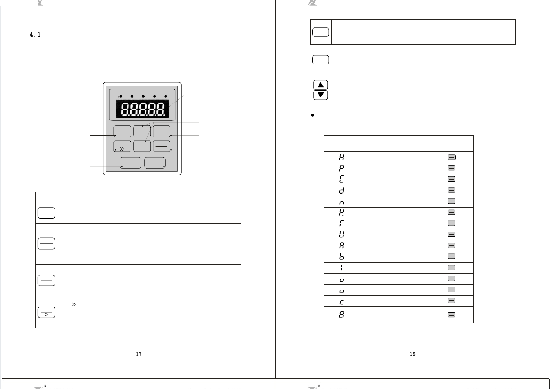
This digital keypad module includes two parts: display panel and a keypad. The display panel
allows the user to program the AC drive, as well as view the different operating parameters. The
keypad is the user interface to theAC mot or drive. Refer to the following figure for a description
of the different parts.
Function indicator
RUN STOP JOG FWD REV
Digital display
Fuling Inve r te r Use r Ma nua l - slide pdf.c om
RUN
Run
Used tos tart theAC drive operation.
This key has no effect when the drive is set to terminal run.
STOP
Stop
Used tos top theAC drive operation.
If the AC drive has stopped due to a fault, press this button to reset the drive.
Up / Down
Press the "Up" or "Down" button to change parameter settings .
These keys may also be used to scroll through different operating val ues or parameters.
Forward / Reverse key
Jog key
Run key
FWD
REV
JOG
▲ PRGM
RESET
▲ FUNC
DATA
RUN STOP
Up and down keys
Program key
Function / Data key
Stop / Reset key
Fig. 4-1 Operation Panel Schematic Diagram
Key
PRGM Program / Reset
RESET First-stage menu entry or exit.
Description
FUNC
DATA
Function / Data
Displays information on theAC drive status such as the reference frequency,output
frequency, or output current in the normal mode. While the drive is in the Program Mode,
press this key once to display the current paramet ers.
After changing the parameters, press th is key again to store the new parameters.
FW D
RE V
Forward / Reverse
Used to toggle between forward and reverse operation.
Pressing this key will cause the motor to ramp down to 0 Hz and then ramp up to the preset
speed in the opposite direction.
JOG
JOG/
Used to start the AC drive, then run at the jog frequency.
When modify parameter, can select modified bit of the parameter.
Explanation of Screen Display
1. Explanation of Displayed Messages on Running status(refer to F3.05):
Displayed
Symbol
Displayed Message
Operation
Setting frequency
Running frequency
Output current
Output voltage
Running speed
Output power
Output torque
DC bus voltage
PID setpoint
PID feedback
Input terminal status
Output terminal status
VI value
CI value
Current segment of
multi-speed control
Press“ QFUUNICCK ”key
DJAOTGA
Press“ QFUUNICCK ”key
DJAOTGA
Press“ QFUUNICCK ”key
DJAOTGA
Press“ QFUUNICCK ”key
DJAOTGA
Press“ QFUUNICCK ”key
DJAOTGA
Press“ ”key QFUUNICCK
DJAOTGA
Press“ QFUUNICCK ”key
DJAOTGA
Press“ QFUUNICCK ”key
DJAOTGA
Press“ QFUUNICCK ”key
DJAOTGA
Press“ ”key QFUUNICCK
DJAOTGA
Press“ QFUUNICCK ”key
DJAOTGA
Press“ QFUUNICCK ”key
DJAOTGA
Press“ QFUUNICCK ”key
DJAOTGA
Press“ QFUUNICCK ”key
DJAOTGA
Press“ QFUUNICCK ”key
DJAOTGA
-17-
http://slide pdf.c om/re a de r/full/fuling-inve r te r-use r-ma nua l
-18-
12/54

