DZB100 Series
Parameter Settings
F1-43 Digital Output Frequency Multiplier Factor
F1-
43
Parameter Name Digital output frequency multiplier factor
Factory Setting 1
Unit 1
Settings 1 20
This parameter determines the multiplying factor for the AC drive digital output frequency
(+10V pulse, 50% duty cycle) at the digital output terminals (DFM, DCM).
The number of output pulses per second on DFM is equal to the AC drive output frequency
multiplied by F1-43.
F1-44 Analog Output Gain Setting
F1-
44
Parameter Name Analog output gain setting
Factory Setting 100%
Unit 1%
Settings 1 200%
This parameter can be programmed while the drive is running.
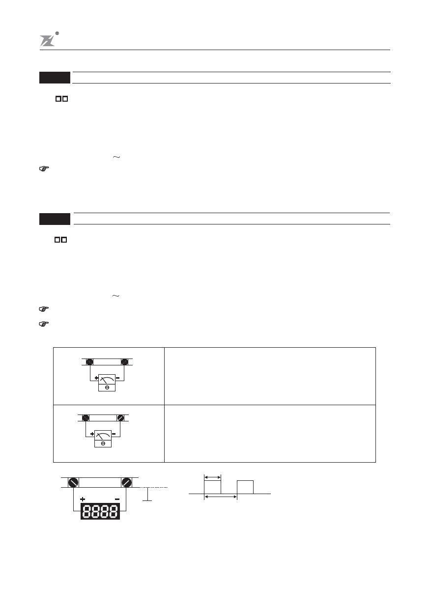
This function regulates the voltage level of the analog signal output (frequency or current)
at the AFM output terminal, which is then fed to the meter.
FM
ACM
Analog frequency meter
FM
ACM
Analog current meter
DFM
DCM
The analog voltage output is proportional to th AC drive
output frequency. The AC drive maximum operating
frequency (F1-03) is equivalent to 10 VDC. If necessary,
adjust the output level using F1-44 Analog Output Gain.
The analog voltage output is proportional to the AC drive
output current. 10 VDC of analog voltage is equivalent to
2.5 times the AC drive rated output current. If necessary,
adjust the output level using F1-44 Analog Output Gain.
T1
DC+10V
Analog frequency meter
T2
T1 / T2 (duty cycle) = 50%
The number of output pulses per second is equal
to the output frequency multiplied by [F1-43].
Note: The digital frequency output should be less
than 1.2 KHz.
-47-

