DZB100 Series
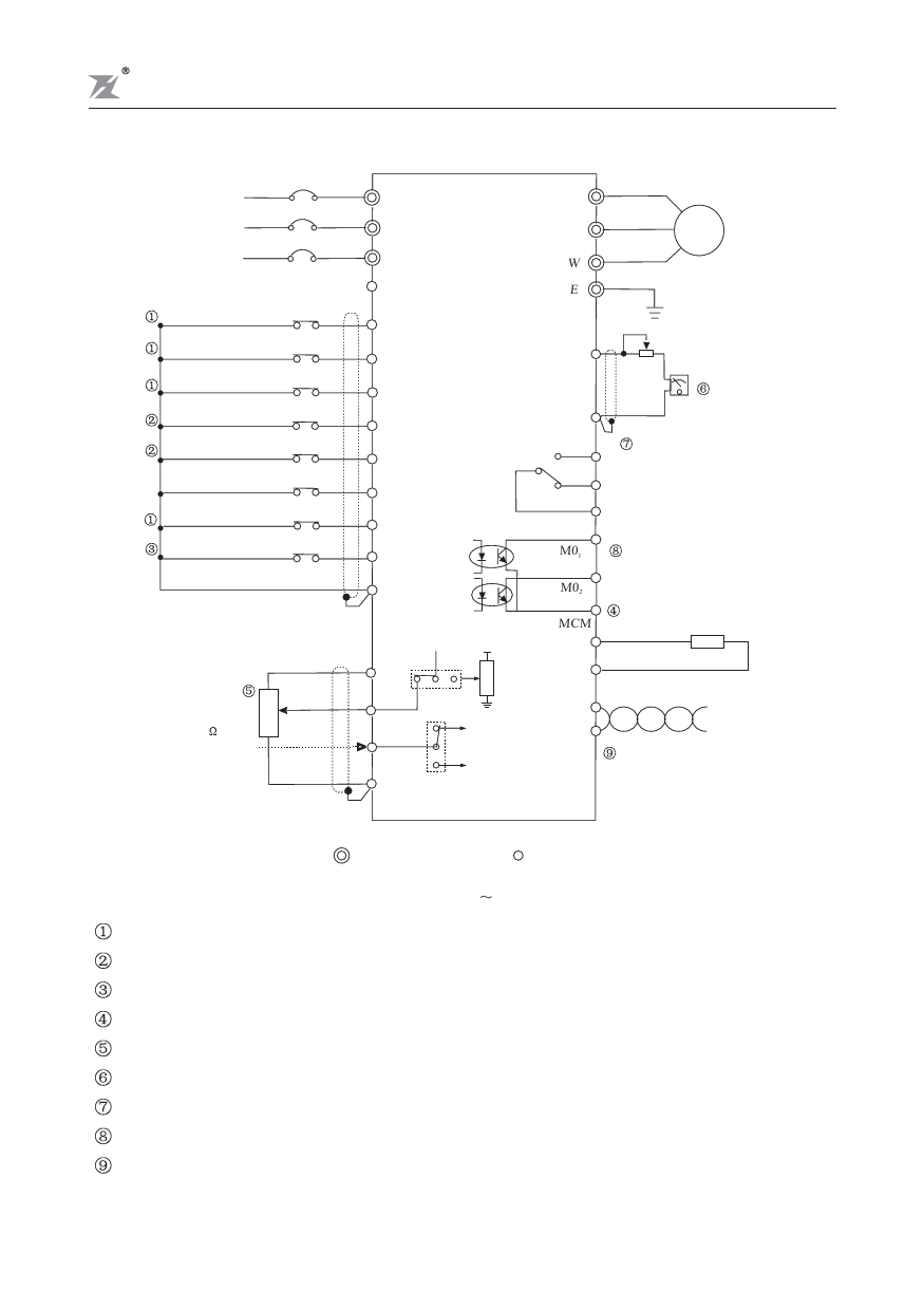
Installation and Wiring
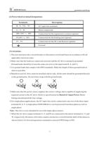
Use a disconnect
and fuse
Power source R
R
3 phase
200-240V or S
S
380-480V
50/60Hz
T
T
DC 20V ~ 24V ( 50mA Max. )
Multi-function input 1
Multi-function input 2
Multi-function input 3
REV/STOP(REV/STOP)
FWD/STOP(RUN/STOP)
Reset
Multi-function input 4
(External fault)
Counter trigger input
Digital signal common
EV
MI1
MI2
MI3
REV
FWD
RST
MI4 (EF)
TRG
DCM
U
V
M
W
E
Grounding
FM
ACM
+
-
Analog frequency/
current meter
DC0-10V
A Multi-function indication
output contact
C AC 250V 2A below
B DC 30V 2A below
M01
Multi-function PHC output
M02 48V 50mA below
Frequency setting
0~10VDC
Vr:3k~5k
Current input
4~20mA
3
2
1
MCU
VCC
MCM Digital frequency meter
DFM
8888
V I WR
10V
DCM
VI
S1
Panel Resistor
SG+
CI
CI
Frequency setting
4~20mA
SG-
ACM
VI
S2
Frequency setting
0~10V
Signal+
Signal-
RS-485 Serial interface
shows main circuit shows control circuit
Notes :
132KW 315KW
Refer to F1-39, 40, 41 on page 45.
Refer to F1-38 on page 44.
Refer to F1-45, 46 on page 48 and F1-63, 64, 66 on pages 55 and 56.
Refer to F1-43 on page 47.
Refer to F1-00 on page 28, F1-48, 49, 50 on page 49.
Refer to F1-42, 44 on pages 46 and 47.
Refer to F1-57 on page 53.
Refer to F1-45, 46 on page 48.
Refer to F1-00, 01 on page 28, F1-77, 78 on page 60 and 61.
-12-

