DZB100 Series
Installation and Wiring
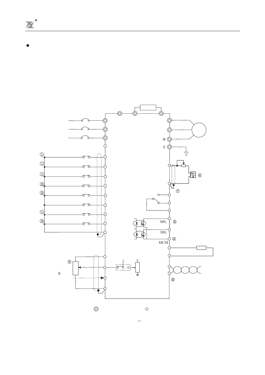
2.3 Basic Wiring Diagram
Users must connect wires according to the following circuit diagram shown below. Do not plug a
Modem or telephone line to the RS-485 communication port, permanent damage may result.
Terminals 1 & 2 are the power sources only for the optional copy keypad and should not be used
while using RS-485 communication.
Use a disconnect
and fuse
Power source R
3 phase
200-240V or S
380-480V
50/60Hz
T
DC 20V ~ 24V ( 50mA Max. )
Multi-function input 1
Multi-function input 2
Multi-function input 3
REV/STOP(REV/STOP)
FWD/STOP(RUN/STOP)
Reset
Multi-function input 4
(External fault)
Counter trigger input
Digital signal common
Braking resistior(option)
R
S
T
EV
MI1
MI2
MI3
REV
FWD
RST
MI4 (EF)
TRG
DCM
BR+ BR-
U
V
W
E
M
Grounding
FM
ACM
+
-
Analog frequency/
current meter
DC0-10V
A Multi-function indication
C
output contact
AC 250V 2A below
B DC 30V 2A below
M01
Multi-function PHC output
M02 48V 50mA below
Frequency setting
0~10VDC
Vr:3k~5k
Current input
4~20mA
3
2
1
MCM Digital frequency meter
DFM
8888
10V MCU
VI V I WR
VCC
DCM
Panel Resistor SG+
CI
SG-
Signal+
Signal-
ACM
RS-485 Serial interface
shows main circuit shows control circuit
0.75KW 5.5KW
-10-

