Shenzhen Reader Technology Co., Ltd
3 Description of Interface Signal for MainBoard
3.1 Interface of Main Power Source JP1
Pin
1
2
3
4
Caution
Symbols
+24V
GND
GND
NC
Definitions
24V power positive (input)
24V power ground (input)
24V power ground (input)
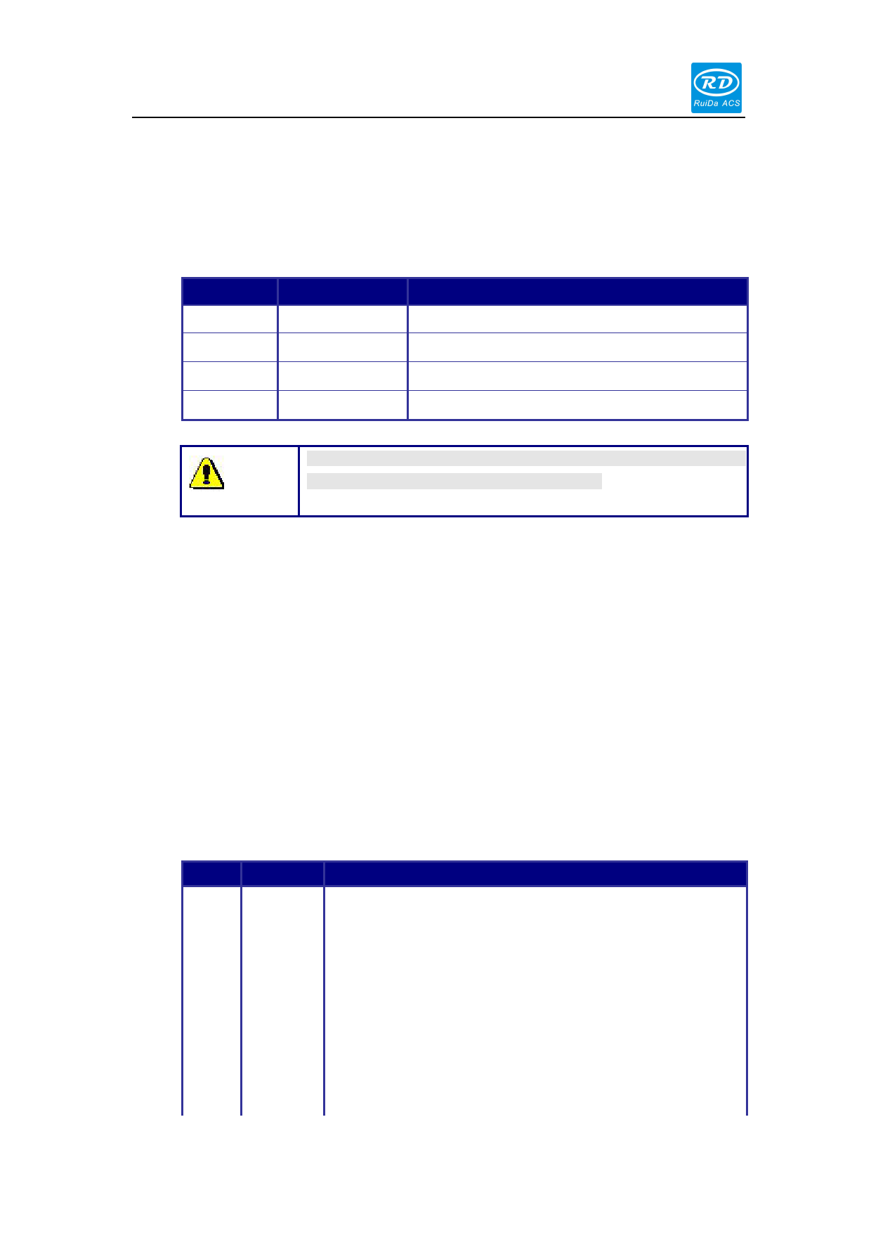
This control system employs single 24 power supply. For a certain
margin, it is suggested to select 24V/2A power.
3.2 Udisk Interface
Udisk is a USB-AM interface. The controller may visit the u-disk by this interface.
3.3 PC-USB Interface
PC-USB is a USB-BM interface. The controller may communicate with PC by this port.
3.4 Special IO port
The Special IO port is defined as follows:
Pin
Symbols Definitions
1
GND
Power ground (output)
2
DrProc Input from protective port. If the machine needs to be protected in
the special state (such as door open protection), the protective
signal can be inputted from this pin. This pin can be enabled and
prohibited. This signal is not inquired by the mainboard if this pin is
prohibited; if this pin is enabled, when the input is high-leveled or
this input port is suspended, the machine will be protected, the
work suspended and the laser closed.
3
FootSW Input port of foot switch. The connection method is: when the
pedal is stepped down, the low-level signal will be inputted to this
4

