
Part 5. Indicator Lights:
The top red light (D1) is constantly on, indicating that the controller is operating in intelligent control mode.
The top red light (D1) is off, indicating that the controller is operating in constant temperature mode.
The top red light (D1) is flashing, indicating that the controller is operating in parameter setting mode or displaying the
room temperature value.
The bottom red light (D2) is constantly on, indicating the cooling state.
The bottom red light (D2) is off, indicating the micro-cooling state.
The bottom red light (D2) is flashing, indicating the non-cooling state.
Part 6. Key Sounds
When a key on the controller is pressed, a short sound will be emitted as a key confirmation.
Part 7. Power-On Display:
After power-on, the display panel should flash for 3 seconds, simultaneously showing the indicator lights and the digital
display (including D1, D2, and the date: day).
Part 8. Room Temperature and Water Temperature Calibration
If there is a deviation between the displayed temperature (room temperature or water temperature) and the actual
temperature, it can be adjusted using A4 and A5 for calibration.
Part 9. Upon Power-On
After the power-on delay (A2) time, the temperature controller enters a 100% full-power cooling state for 25 seconds.
Then, it controls the operation of the chiller based on the actual air temperature and water temperature. (Note: This
functionality can be defined as "short-term cooling on startup." If, after the short-term cooling on startup, the water
temperature is higher than the water temperature set value minus the heating hysteresis, the compressor does not stop.
This functionality is designed to facilitate maintenance and servicing work.)
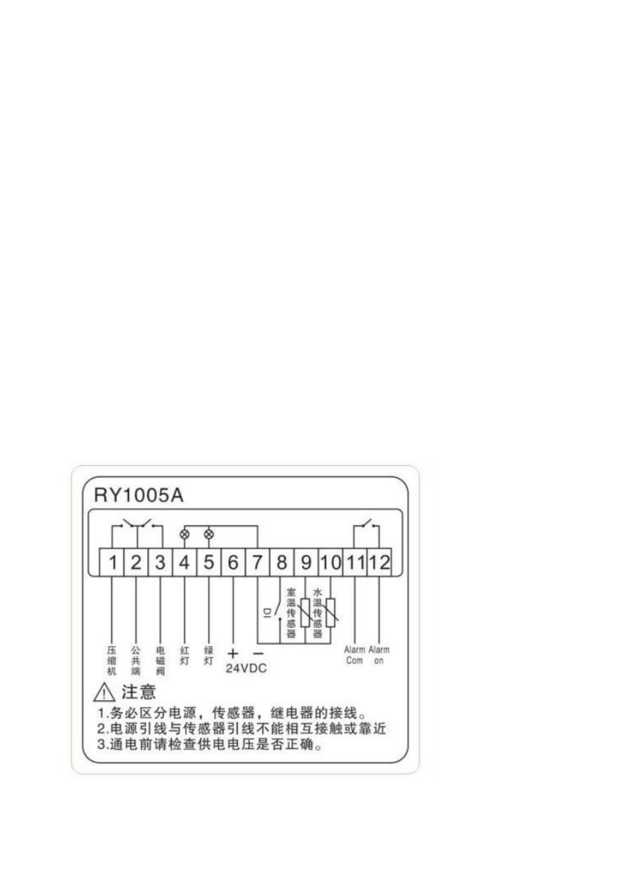
Part 10. Controller Wiring Diagram.
 Chiller Temperature Controller RY1005A Manual")
 Chiller Temperature Controller RY1005A Manual")
 Chiller Temperature Controller RY1005A Manual")
 Chiller Temperature Controller RY1005A Manual")
 Chiller Temperature Controller RY1005A Manual")