
How to set delay time:
Display
Description
PV
Upper line displays measured temperature
SV
Lower line displays time set value
Operation
Press “< ” key to enter time
setting mode
PV
Upper line displays TV
Press “∧” or“∧”, to add or minus
SV
Lower line displays time set value
TV value
PV
Upper line displays TV
Hold “∧” or“∧”, to add or minus
SV
Lower line displays time set value
SV value continuously
PV
Upper line displays measured temperature Press “SET” to return to working
SV
Lower line displays time set value
mode.
Description of time delay process
Display
Description
Operation
PV
Upper line displays measured temperature Short connect external input contacts,
SV
Lower line displays time set value
to enter time delay control mode
PV
SV
Upper line displays measured temperature
Lower line displays counting down
decrease 1 in every seconds
PV
SV
Upper line displays measured temperature
Lower line displays counting down
After 20 seconds, lower line counts
down to“0”, output time delay,
“END”indicator on the panel turns on
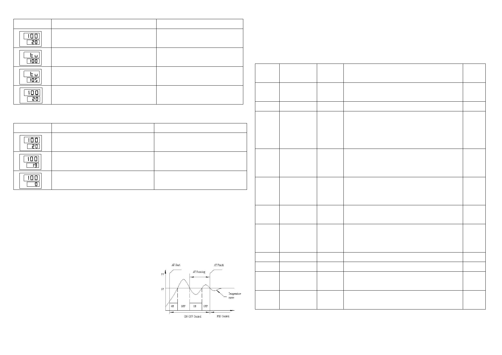
Auto-tuning function
How to start and stop auto-tuning
1. When start auto-tuning, the heating system should be in working status and the measured
temperature should be lower than setting value.
2. Press SET key for 5 seconds to enter parameter setting mode. Click SET key until “LCK” appears,
set LCK=1. Click SET key until “AT” appears and input auto-tuning type (1, 2, 3 optional,
usually choose 1). Press SET key for about 5 seconds, AT indicator light flashes. Auto-tuning is
running.
3. press minus key“Ⅴ”for 5 about seconds to enter auto-tuning status directly
When auto-tuning is accomplished, AT indicator light turns off. The controller has calculated out
a group of parameters fit to the system and would run
under the new PID parameters.(New PID parameters
could be found in the controller system.)
Remark: auto-tuning functions (AT) are sorted into 1, 2,
3 types
1). AT=1 means No.1: general type, fast temperature
rise and excellent stability.
2). AT=2 means No.2: overshoot suppression type,
suitable for the quick system which can’t achieve short
heating cycle.
3). AT=3 means No.3: lag/delay system type, especially
suitable for those systems which are hard to bring down the temperature after overshooting
3
Parameter explanation
1. In PID data setting mode, press SET key each time; data in following table shall be displayed in
sequence. However, based on the specifications when placing the order, some data may not appear
and the initial value could be different.
2. If user needs ON-OFF control, set P=0 and D= return difference (0.1°C)
Para-
meter
Name
Setting
Description
Defau
lt
P
Proportional
0~99.9 Set proportional band of heating end ( when 027
Band(Heat)
%
Pv=0, it is stepping control)
I
Integral Time 0-250
Integral Time for heating end (re-adjust time)
031
D
Differential
0~999
Differential Time for heating end (advance adjust 005
Time
time).
When it is ON-OFF control, D parameter is return
difference
IT
Overshoot
0~200
The smaller is IT value, the smaller is the first 005
suppression
overshoot, but it takes longer to reach the set
temperature value.
SP
Proportion
0~200
To prevent overshoot caused by proportion 0
band
function.
separate
T
Output cycle 1~180
Set the cycle time for the output of the controller 008
(Heat)
sec
(heat)
TR
Temperature -99~100 Set Temperature modification parameter when 0
modification
there are affection caused by the position of sensor
or other factors
AH
Alarm value 1 0~100
Set alarm parameter
010
RAG
Upper limit
0~999
Set upper limit for temperature
400
AT
auto-tuning 1,2,3
auto calculate PID parameter to fit the user’s 000
system
LCK
data lock
0,1
When LCK=000, all parameters are locked; when 000
LCK=001, parameters could be modified.
4
 XMTD-2MB-YS Series Temperature Controller Operation Manual")
 XMTD-2MB-YS Series Temperature Controller Operation Manual")