Page 3 of 5
White Paper
Measurement Illumination Condition M1
Measurement illumination condition M1 was defined to reduce variations in measurement results between instruments due to
fluorescence, either by optical brighteners in paper or fluorescence of the imaging colorants or proofing colorants. M1 (Part One)
specifies that the spectral power distribution of the light source used to measure the specimen should match CIE Illuminant D50. M1
also defines a second, (Part Two) method for achieving M1 compliance that is only valid for measuring optically brightened papers but
not for measuring inks or toners that fluoresce. This is due to the historical complexity of delivering a true D50 illumination in handheld
instruments. This second definition only requires that a compensation method is used with a controlled adjustment of the amount of UV
component (spectral region below 400 nm) used to measure. This is to provide correlation to the D50 illumination conditions as defined
in ISO 3664:2009 viewing standard. This second method must be tied to a viewing condition compliant to ISO 3664:2009, so caution
in using it must be exercised, and testing for agreement is advised.
Measurement Illumination Condition M2
For the first time, an ISO standard defines what UV exclusion (variously known as UV-cut, No UV, or UV-filtered) should be in a
measurement tool. M2 also provides a test to ensure compliance to the standard. Instrument manufacturers now have a defined way
to provide agreement when customers require an instrument that does not contain UV. We will be able to measure papers containing
optical brightening agents and communicate color data with greater precision and consistency. X-Rite, as part of its XRGA efforts, has
made sure that all new UV-cut products meet this definition.
Measurement Illumination Condition M3
M3 defines the effect of polarization. In essence, M3 requires the UV-restricted properties of M2 and adds a definition of polarization.
Polarization is used in certain measuring instruments to remove or minimize reflections. Polarization is usually accomplished by
choosing a polarization function or adding an optional manufacturer-specific polarizing filter. X-Rite, as part of its XRGA efforts (see
below), has insured that its instruments offering M3 mode (polarization filter) provide a UV level that is compliant with the new standard.
Applications and use of M0, M1, M2, and M3
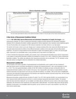
In theory, the cases where each of these measurement illumination conditions are used are relatively clear:
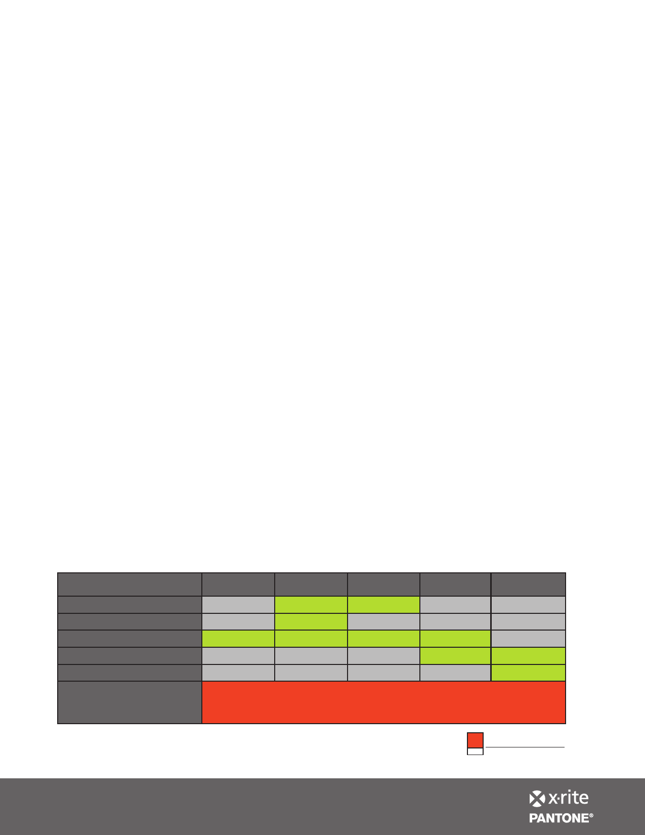
• M0 is for any use where neither substrate nor imaging colorants fluoresce.
• M1, part 1, is intended for use when either substrate or imaging colorants, or both may fluoresce.
• M1, part 2, is designed for use when a substrate may fluoresce, the fluorescing characteristic needs to be captured, and the user
is confident that the imaging colorants do not fluoresce. (When in doubt, consulting with the ink manufacturer is recommended.)
• M2 is for use when the paper fluoresces, but there is a desire to eliminate this effect from affecting the data.
• M3 is for special use cases where first surface reflections should be minimized, including the use of polarization to do so.
Measure effect of OBAs
Measure ink fluorescence
Measure non-OBA stock
Cut the effect of OBAs
Cut first surface reflections
Agree on M standard for use
in exchanging data prior to
measurement
M0
M1
M1
M2
M3
1
2
3
3
3
3
3
3
3
3
3
3
When using any M standard to exchange data, it is essential to agree on a
particular M standard before measuring data.
2012 COLOR OF THE YEAR
PANTONE® 17-1463
Tangerine Tango
X-Rite World Headquarters
Grand Rapids, Michigan USA • +1 800 248 9748 • +1 616 803 2100 • xrite.com
© 2011 X-Rite, Incorporated. All rights reserved. L7-510 (01/12)

