______ HSD __________________________________________________________________________________
2.4 TOOL FITTINGS
Various types of tool fittings are available to cover most applications. (See data sheet.) These include:
1. spindle shaft with flexible collet
2. spindle shaft with cylindrical fitting, key and externally threaded head
3. spindle shaft with cylindrical fitting, key and internally threaded head
4. spindle shaft with special fitting
All tool fitting types are manually operated. The operator must only fit tools with the spindle shaft stationary.
Tools can be locked by ring nuts, screws, or by expansion systems. Drive is transmitted from the spindle shaft to the tool
either by friction (close contact) or by a key.
To lock the tool in the spindle, fit a key in the hexagonal holes accessible through the fan cover on some electro-spindle
models or to the flats on the spindle shaft of other models to stop the spindle turning while tightening the tool in place.
(See data sheet.)
Certain types of electro-spindle are fitted with a spring loaded pin which can be pushed in to lock the shaft. On these
models, turn the shaft slowly by hand while pushing the pin in until it engages.
MAKE SURE THAT THE RING NUTS AND THE TOOL ARE TIGHT BEFORE STARTING THE ELECTRO-SPINDLE.
ON VERSIONS FITTED WITH A TOOL ENGAGEMENT KEY, NEVER START THE ELECTRO-SPINDLE WITHOUT A TOOL IN
PLACE AND CORRECTLY TIGHTENED.
ON VERSIONS FITTED WITH A SHAFT LOCKING PIN, MAKE SURE THAT THE PIN IS FULLY DISENGAGED FROM THE SHAFT
BEFORE STARTING THE ELECTRO-SPINDLE. ALSO ALWAYS MAKE SURE THAT THE ELECTRO-SPINDLE IS FULLY
STATIONARY AND NOT POWERED ON BEFORE TURNING THE SHAFT AND ENGAGING THE PIN.
In relation to the tool with manual HSK connection device, follow the instructions given below to ensure
perfect assembly and avoid damage to the motor:
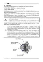
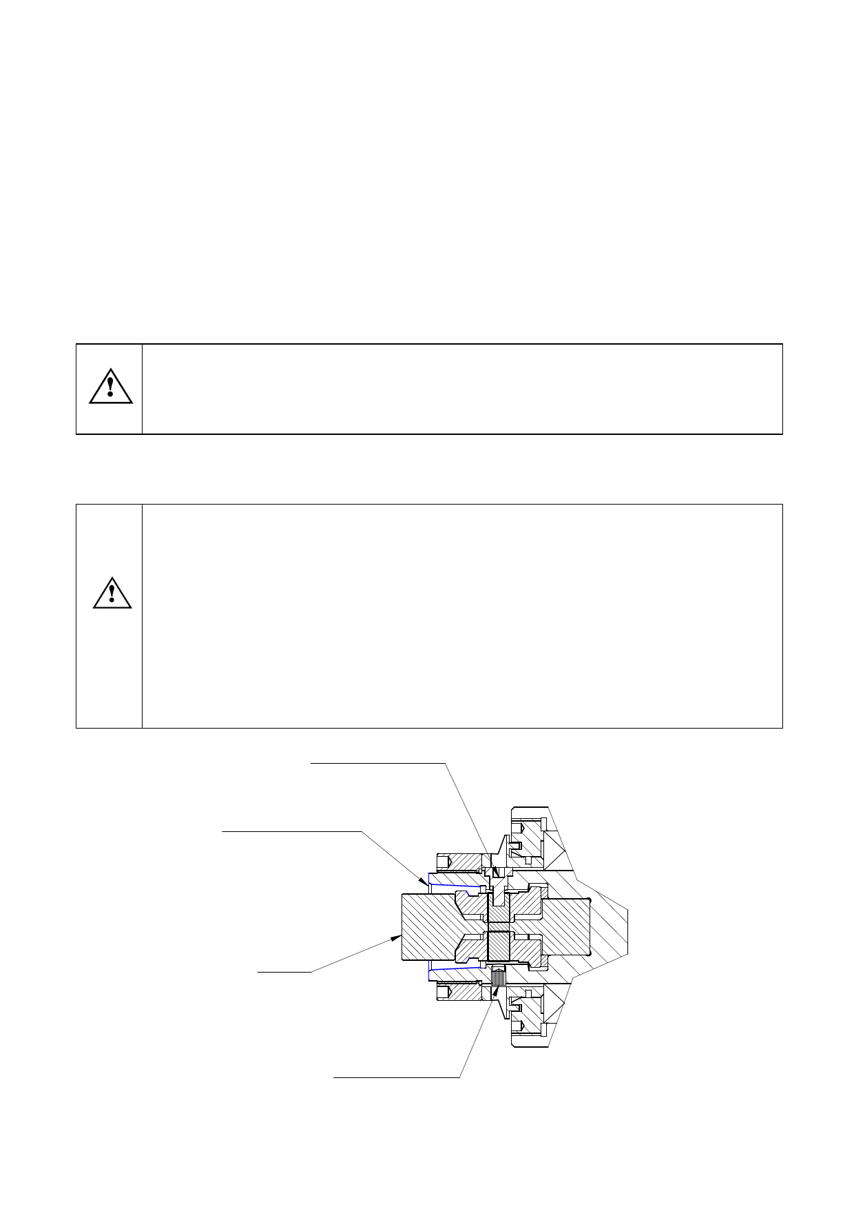
TO VERIFY THE CORRECT ASSEMBLY OF THE TOOL HOLDER, IT IS IMPORTANT TO CHECK THAT
WHEN IT IS ASSEMBLED, THERE IS NO LIGHT BETWEEN THE FRONT FACE OF THE SHAFT AND THE
TOOL HOLDER. IT IS VERY IMPORTANT TO KEEP THE COUPLING SURFACES CLEAN, ALONG WITH
THE TOOL HOLDER, CONE, THE FRONT FACE OF THE SHAFT AND THE PULL SPLAY OF THE COLLET
(SEE BLUE PARTS OF FIGURE 2.2).
THE COMMAND SCREW IS USED TO OPEN AND CLOSE THE SPLIT COLLET THAT DRAGS THE TOOL
HOLDER TO CONTACT WHEN IT IS INSERTED ON THE SHAFT. USE A TIGHTENING TORQUE OF 4NM.
AT 180° FROM THE TIGHTENING SCREW, THERE IS A LOCKSCREW BLOCKED WITH A THREAD
BRAKE THAT ACTS AS A PLUG. BY REMOVING THIS LOCKSCREW, YOU CAN WORK ON THE SPLIT
COLLET TO OPEN AND CLOSE IT. THIS SOLUTION IS ONLY USED WHEN THE TIGHTENING SCREW IS
BROKEN, SO AS TO UNBLOCK THE TOOL HOLDER AND PROCEED WITH THE DISASSEMBLY OF THE
UNIT AND THE REPLACEMENT OF THE TIGHTENING SCREW.
THE MOTOR SHOULD NOT BE TURNED WITHOUT THE LOCKSCREW DESCRIBED ABOVE, AS IT
WOULD BE IMBALANCED.
Vite di comando Ch 4
Locking screw Ch4
Zona blu da tenere pulita
Bleu zone to clean
Pinza HSK
HSK clamp
Grano di sicurezza M5
Security lockscrew M5
Y580100001 rev.03 _____________________________________________________________________ 6

