- You are here:
- AM.CO.ZABuythisCNC Utilities Homepage
- EasyRoute-CNC-Router
- Component Manuals
- VICSION VS500 Inverter Manual.pdf
- Page 99 of 113
10. USAGE EXAMPLE
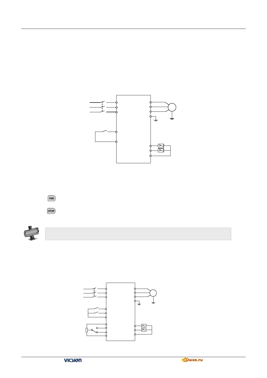
10.1 Panel on-off control, Panel potentiometer setting frequency
10.1.1 Parameters setting
1. When F0.4 is 00#0, panel control is valid.
2. When F0.1 is 3, panel potentiometer is valid
10.1.2 Basic wiring
3-phase Breaker
Power
Supply
×
R
×
S
×
T
Motor
U
V
M
W
E
Duxe.ru VICSION VS500 95
Direction
control
FWD
CM
AO1
AO2
GND
Voltmeter (0~10V)
Voltmeter (0~10V)
Fig10-1 Basic wiring
10.1.3 Operation Notes:
Press
key to start the inverter, and then rotate the button of panel potentiometer in clockwise to increase
setting frequency step by step. Contrarily, rotate in anti-clockwise to decrease setting frequency step by step.
Press
key to stop the inverter.
External control terminal FWD decides the running direction of motor.
10.2 External on-off control mode, external voltage setting frequency
10.2.1 Initial setting
1. When F0.4 is 00#1, external terminals control is valid.
2. When F0.1 is 5, external voltage VC2(0~10V) is valid
10.2.2 Basic wiring
3-phase Breaker
Power
×
R
U
Supply
×
S
V
×
T
W
E
FWD
REV
10K
FWD
REV
CM
VS
VC1 (0~5V)
VC2 (0~10V)
GND
AO1
AO2
GND
Motor
M
Voltmeter (0~10V)
Voltmeter (0~10V)
Fig10-2 Basic wiring
VS500 series of general purpose inverter Duxe.ru

