4 VICSION VS500
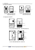
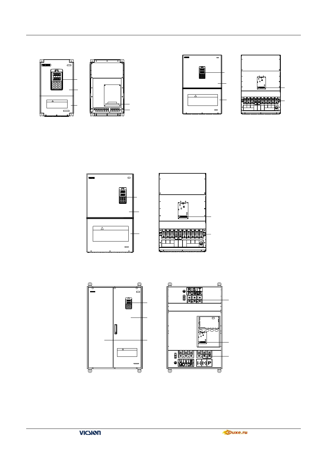
1.2.2 Appearance of model II
V S50 0
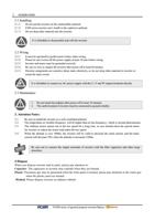
! W ARNING
1.Ref er to t he i nst ruc tion m anual bef ore i nst allat ion
and o perat ion.
2.Do not c onnec t AC power t o out put term inals UV W.
3.Do not rem ov e any cov er while ap plyi ng power
and at leas t 10m in. af ter d isc onnec t ing power.
4.S ec urely ground(earth) the equipm ent.
O perat ion
panel
Upper
cover
Lower
cover
Contro l term inals
M ain circuit terminals
It is fit for:VS500-4T0110~VS500-4T0750
VS500-2T0055~VS500-2T0370
1.2.3 Appearance of model III
VS5 00
Operation panel
Upper cover
! WARNING
1.Refer to the instruction manual before installation and
operation.
2.Do not connect AC power to output ter minals UVW.
3.Do not r emove any cover while applying power and
at leas t 10min. after disc onnecting power.
4.Securely gr ound(earth) the equipment.
Lower cover
P R S T
POWER 电源
(+) (-) U V W
MOTOR 电机
Control terminals
Main terminal
It is fit for:VS500-4T0900~VS500-4T1320
VS500-2T0450~VS500-2T0750
V S500
Operation panel
! WARNING
1.Refer to the instruction manual before installation and
operation.
2.Do not connect AC power to output terminals UVW.
3.Do not remove any cover while applying power and
at least 10min. after disconnecting power.
4.Securely ground(earth) the equipment.
Upper cover
Control terminals
Lower cover
P R S T (+) (-) U V W
POWER µ çÔ ´
MOTOR µ ç» ú
Main circuit terminals
It is fit for:VS500-4T1600~VS500-4T2200 VS500-2T0900~VS500-2T1100
VS 500
R UN
Hz
A
V
ESC
JOG
<<
SET
REV
FWD
UP
DOWN
STOP
Operation
panel
Right door
! WARNING
1. Ref er t o the instruction manual before i nst al lation
and operation.
2. Do not connect A C power to out put terminals UVW.
3. Do not remove any cover while applying power
and at least 10min. af ter disconnecting power.
4. Securely ground(earth) the equipment .
Left door
Terminal of main
circuit
terminal of
control circuit
Terminal of main
circuit
It is fit for:VS500-4T2500~VS500-4T3150 VS500-2T1320
VS500 series of general purpose inverter Duxe.ru

