- You are here:
- AM.CO.ZABuythisCNC Utilities Homepage
- EasyRoute-CNC-Router
- Component Manuals
- VICSION VS500 Inverter Manual.pdf
- Page 92 of 113
88 VICSION VS500
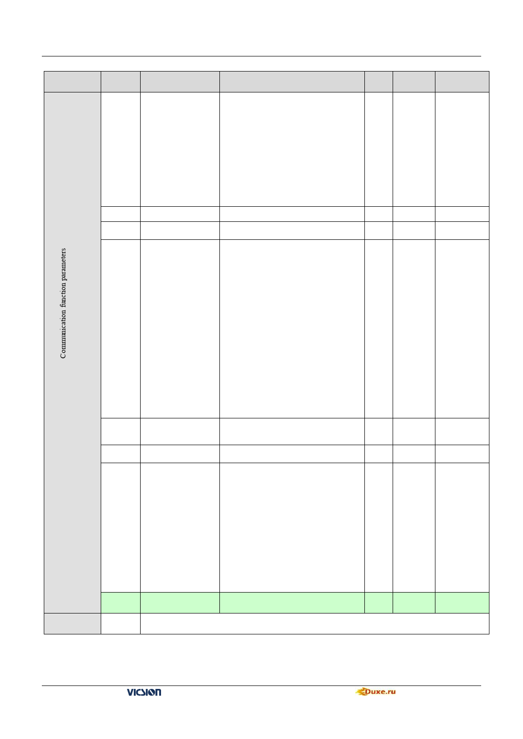
Parameter
Type
Code
Name
F9.0
Communication
setting
F9.1 Local address
Response delay of
F9.2
local
Function setting of
F9.3 communication
Auxiliary function
Probable Causes
The first part of LED(form right to left):
It is used to set baud rate of serials
Communication.
0: Reserved 1:1200bps 2: 2400bps
3: 4800bps 4: 9600bps 5: 19200bps
The second part of LED:
To set data format of serials
communication.
0:Close 1: Even 2:Odd
The third and fourth part of LED:
Reserved.
0~30
0~1000 ms
The first part of LED(form right to left):
0:The inverter is guest
1: The inverter is host
The second part of LED: Act selection
after
communication is lost
0:Stop 1:Keep
The third part of LED:linkage jog
0:jog synchronized
1:jog asynchronous
The fourth part of LED:linkage control
synchronized frequency source
0:setting frequency
1:output frequency
Min. Factory
Unit Value
1
0014
1
0
1
5ms
1
0010
Modification
Limited
★
Checkout time of
F9.4 communication
overtime
F9.5
Linkage setting
proportion
Rectify channel of
F9.6 linkage
setting proportion
0.0~100.0 Sec
0.1
0.010~10.000
0.01
0:close 1:Panel potentiometer
Rectify channel 2:External voltage signal
VC1
(0 ~ 5V)
Rectify channel 3:External voltage signal
VC2
1
(0 ~ 10V)
Rectify channel 4:External current signal
CC
(0 ~ 20mA)
10.0
1.000
0
F9.7 ~
F9.11
FC.0 ~
FC.5
Reserved
The same with the general definition of parameters, please refer to the general parameter table
VS500 series of general purpose inverter Duxe.ru

