Duxe.ru VICSION VS500 75
It defines waiting time, which is the time form local receives correctly code to send response data frames
F9.3 Function setting of communication Auxiliary function
The first part of LED(form right to left):
0: The inverter is slave
1: The inverter is master
The second part of LED: Act selection after communication is lost
0: Stop
1:Keep
The third part of LED:Linkage jog
0:Jog synchronized
1:Jog asynchronous
The fourth part of LED:Linkage control synchronized frequency source
0:Setting frequency
1:Output frequency
Setting range:0000 ~ 1111
F9.4 Checkout time of communication overtime
Setting range:0.0 ~ 100.0 Sec
If the machine itself doesn’t receive correct data signals in regulate time, the communication is fault. Inverter will keep
on running or stop according to setting of parameter F9.3
F9.5 linkage setting proportion
F9.6 Rectify channel of linkage setting proportion
Setting range: 0.010 ~ 10.000
Setting range: 0 ~ 4
It is used for setting proportion of output freq. between master and slave, when takes linkage setting control. When F9.6
is 0, rectify channel of linkage setting proportion is invalid.
Slave freq. = Master freq. × [F9.5]
When F9.6 is 1, 2, 3 or 4, rectify channel of linkage setting proportion is valid. When the lower limit value of rectify
channel is selected, The rectify coefficient is 0.5; when the upper limit value of rectify channel is selected, the rectify
coefficient is 2.0,
Slave freq. = Master freq. × [F9.5] ×rectify coefficient(0.50~2.00)
F9.6 is used for selecting rectify channel. Rectify channel 1:Panel potentiometer
Rectify channel 2:External voltage signal VC1(0 ~ 5V) Rectify channel 3:External voltage signal VC2(0 ~ 10V)
Rectify channel 4:External current signal CC(0 ~ 20mA)
F9.7 Setting channel of guest inverter auxiliary freq.
F9.8 Amplitude of auxiliary freq
Setting range: 0.010 ~ 10.000
Setting range:0.0~25.00 Hz
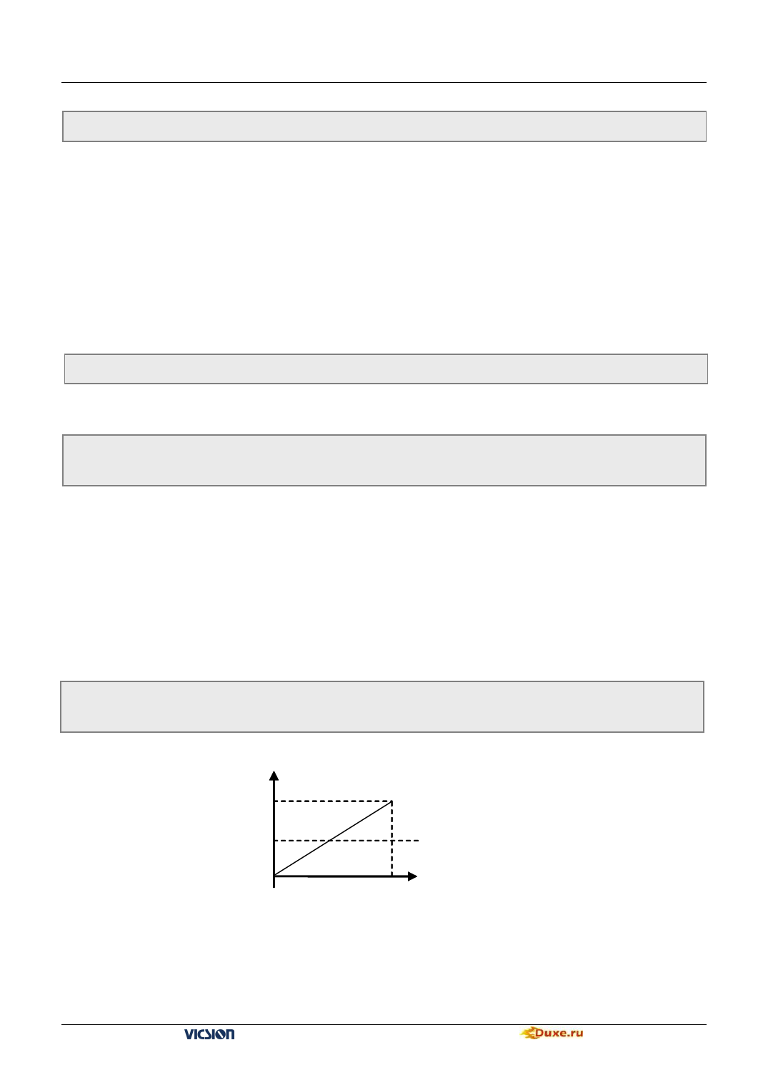
It is used for selecting the setting channel of guest inverter auxiliary freq. and amplitude of auxiliary freq
Auxiliary freq
[F9.8]
-[F9.8]
0
Setting channel input
Fig.6-32 Adjust amplitude of auxiliary freq
When the input value of auxiliary freq. setting channel is middle value,auxiliary freq. is 0, Slave output freq. =
master instruction freq. ×linkage proportion+auxiliary freq. (Linkage proportion is set by [F9.5] 、 [F9.6])
VS500 series of general purpose inverter Duxe.ru
