- You are here:
- AM.CO.ZABuythisCNC Utilities Homepage
- EasyRoute-CNC-Router
- Component Manuals
- VICSION VS500 Inverter Manual.pdf
- Page 76 of 113
72 VICSION VS500
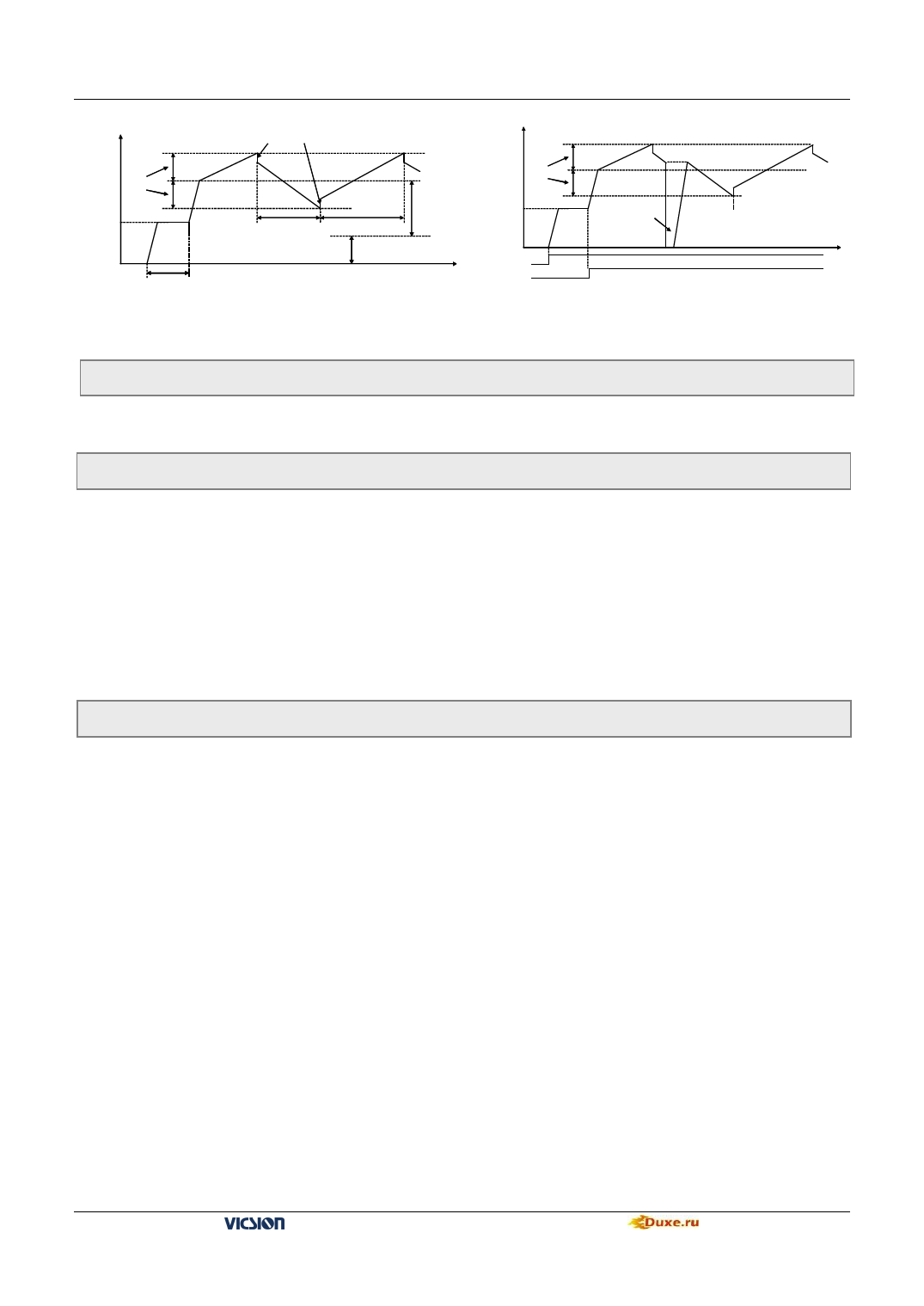
Running freq
[F7.4] ×Amplitude of wobble freq.
Running freq
Amplitude of
wobble freq.
[F7.1]
[F7.6]
[F7.5]
Preset center freq. of
wobble freq.
摆频幅值
[F7.7]
[F7.1]
Break in wobble
freq. and restart
External freq. set by [F0.1]
Running instrument
t
[F7.2]
时间
Wobble freq.
Fig.6-27 Running process of wobble freq
Fig.6-28 Running process of wobble freq
F7.8 Reserved
6.9 PID control parameter unit
F8.0 Inner PID control
Setting range:0000 ~ 1122
The first part of LED(form right to left): Inner PID control
0:Inner PID control is invalid
1:Inner PID control is valid
2:Inner PID control is conditional valid. Inner PID is set by external terminals X1~X6 ( Parameters
F3.0~F3.5)
The second part of LED: PID controller selection
0: proportion 1:Integral
2:Proportion and integral
The third part of LED: Regulating property of PID controller
0: positive interaction
1:Reactor
The fourth part of LED: reserved
F8.1 inner PID setting and channel selection
Setting range:0000 ~ 5705
It is used for setting inner PID and feedback channel.
The first part of LED(form right to left):It is used for setting PID channel 。
0:Digital setting. It is set by parameter F8.2.
1:Serials interface setting
2:Panel potentiometer setting, it is on the operation panel.
3:External voltage signal VC1(0V~5V) 。
4:External voltage signal VC2(0V~10V) 。
5:External current signal CC(0~20mA) 。
The second part of LED: Reserved.
The third part of LED: It is used for setting PID feedback channel.
0:External voltage input VC1 is as feedback channel, which is in the range of 0~5V.
1:External voltage input VC2 is as feedback channel, which is in the range of 0~10V.
2:External current input CC is as feedback channel, which is in the range of 0~20mA.
3:Pulse input PLS is as feedback channel, which is in the range of 0~50 KHz.
4:VC1+CC Feedback value is composed of VC1 and CC
5:VC1-CC Feedback value is that VC1 minus CC.
6:Min (VC1, CC) Feedback value is min value between VC1and CC
7:Max (VC1, CC) Feedback value is max value between VC1and CC
The fourth part of LED: Reserved
VS500 series of general purpose inverter Duxe.ru

