- You are here:
- AM.CO.ZABuythisCNC Utilities Homepage
- EasyRoute-CNC-Router
- Component Manuals
- VICSION VS500 Inverter Manual.pdf
- Page 70 of 113
66 VICSION VS500
F5.24 Running direction of PLC multi-speed
F5.25 Running direction of PLC multi-speed
Setting range:0000 ~ 1111
Setting range:0000 ~ 1111
Parameter F5.0 is multi-speed running mode. It is used for setting basic characteristic of multi-speed running.
The first part of LED(form right to left):Simple PLC selection
0:Simple PLC is invalid.
1:Simple PLC is valid. If priority of freq. channel is permit after starting, inverter will run at simple PLC state
2:Simple PLC is conditional valid. If external X1~X6 terminals is valid (F3.0~F3.5 is set as 22), inverter will
run at simple PLC state.
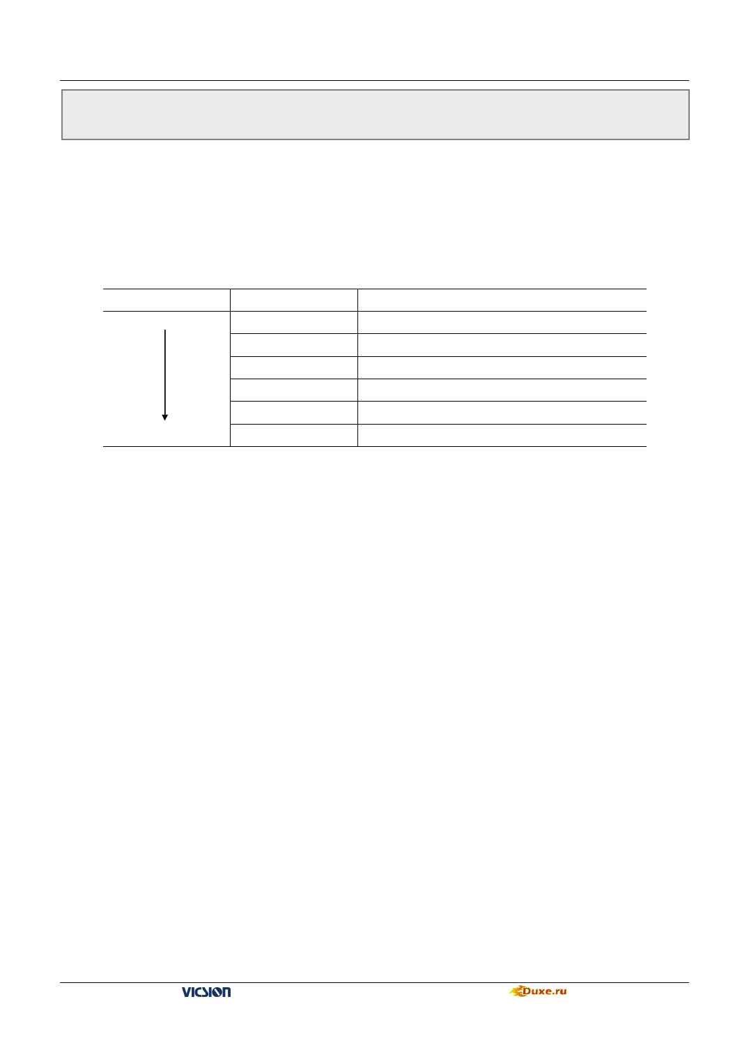
Priority of freq. channel is shown as following table:
Priority grade
High
Priority
1
Setting freq
JOG freq.
2
Wobble freq. running
3
PID output
4
PLC multi-speed freq
5
External terminals select multi-speed freq
Low
6
Freq. setting channel selection(Parameter [F0.1] )
The second part of LED:Simple PLC running mode selection
0:Single loop mode
The inverter will run in setting freq of the first stage and in turn output freq. of each stage according to setting
running time. If setting running time of a certain stage is 0, the inverter will skip this stage. When a cycle operation is
end of run, inverter will stop input until user input available running instrument to restart a next cycle.
1:Single loop and stop mode
Its function has an analogy with single loop mode. The difference is that output freq. is be reduced to 0 within the
given decelerate time after a certain stage is end of run and inverter will run next stage.
2:Continuous loop mode
Inverter will run eight stages in turn. If the eighth stage is end of run, the inverter will run the next cycle form the first
stage.
3:Continuous loop and stop mode
Its function has an analogy with Continuous loop mode. The difference is that output freq. is be reduced to 0 within the
given decelerate time after a certain stage is end of run and inverter will run next stage.
4:Keep the end value
Its function has an analogy with single loop mode. The difference is that inverter will run in the last stage with
non-zero speed.
5:Keep the end value and stop mode
Its function has an analogy with keep the end value. The difference is that inverter will reduce the output freq. to 0 after
arriving setting value of Acc time after a certain stage is end of run and, then inverter will run the next stage
The third part of LED
0:Restart from the first stage freq.
When inverter stop, caused by fault or receiving stop instrument in PLC running, it will clear current running state and
restart form the first stage freq.
1:Restart from running freq., which is saved before the running is breaking.
When inverter stop, caused by fault or receiving stop instrument in PLC running, inverter will restart from running
time and freq. that is saved before the running is breaking.
VS500 series of general purpose inverter Duxe.ru

