- You are here:
- AM.CO.ZABuythisCNC Utilities Homepage
- EasyRoute-CNC-Router
- Component Manuals
- VICSION VS500 Inverter Manual.pdf
- Page 60 of 113
56 VICSION VS500
F2.14 the lower limit of analog output AO1
F2.15 the upper limit of analog output AO1
Setting range: 0.0 V/0.0mA ~ [F2.15]
Setting range: [F2.14] ~ 12.0 V/24.0mA
F2.16 the lower limit of analog output AO2
F2.17 the upper limit of analog output AO2
Setting range: 0.0Hz ~ [F2.9]
Setting range:[F2.16] ~ 12.0 V/24.0mA
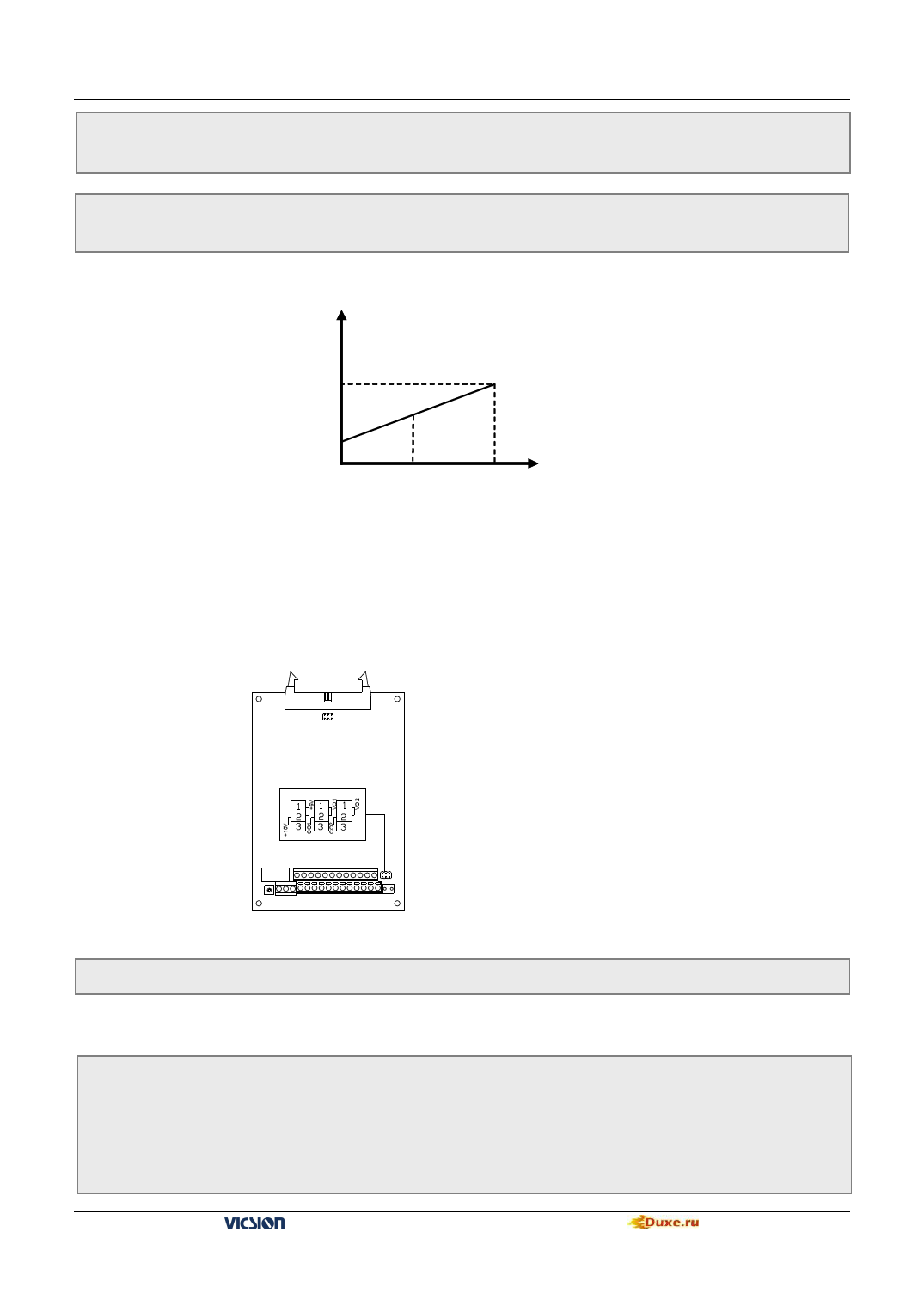
Those parameters define the max and min value of analog output AO1and AO2, shown as fig 6-11
AO1/AO2
[F2.15]
[F2.17]
[F2.14]
[F2.16]
1
2
3
4
5
6
Upper limit voltage Output freq
Rated current
Output curren
The max/rated Voltage Output voltage
Rotor speed
10.00 PID setting
10.00 PID feedback
Fig.6-11 output of analog terminals
AO1 and AO2 provide voltage signal from 0 to 12V or current signal from 0 to 24 mA. Two kinds of output signal
can be selected by JP (JP1 and JP2) switch. JP1 and JP2 are shown as fig.6-12
JP1 JP2 JP3
JP2:
1-2 shorted:AO1 output voltage signal;
2-3 shorted:AO1output current signal;
JP3:
1-2 shorted:AO2 output voltage signal
2-3 shorted:AO2 output voltage signal
F2.18 Reserved
Fig.6-12 JP2/JP3 terminal
6.4 Digital O/I parameter unit
F3.0
F3.1
F3.2
F3.3
F3.4
F3.5
Function selection of input terminal 1
Function selection of input terminal 2
Function selection of input terminal 3
Function selection of input terminal 4
Function selection of input terminal 5
Function selection of input terminal 6
Setting range:0 ~ 26
Setting range:0 ~ 26
Setting range:0 ~ 26
Setting range:0 ~ 26
Setting range:0 ~ 26
Setting range:0 ~ 26
VS500 series of general purpose inverter Duxe.ru

