- You are here:
- AM.CO.ZABuythisCNC Utilities Homepage
- EasyRoute-CNC-Router
- Component Manuals
- VICSION VS500 Inverter Manual.pdf
- Page 58 of 113
54 VICSION VS500
[F2.4] and [F2.5] define the range of analog input current channel CC, and it should be set according to the actual
input signal.
[F2.6] and [F2.7] define the freq. range of external pulse signal
F2.8 frequency with the min setting
F2.9 frequency with the max setting
Setting range: 0.0Hz ~ [F2.9]
Setting range: [F2.8] ~ 600.0Hz
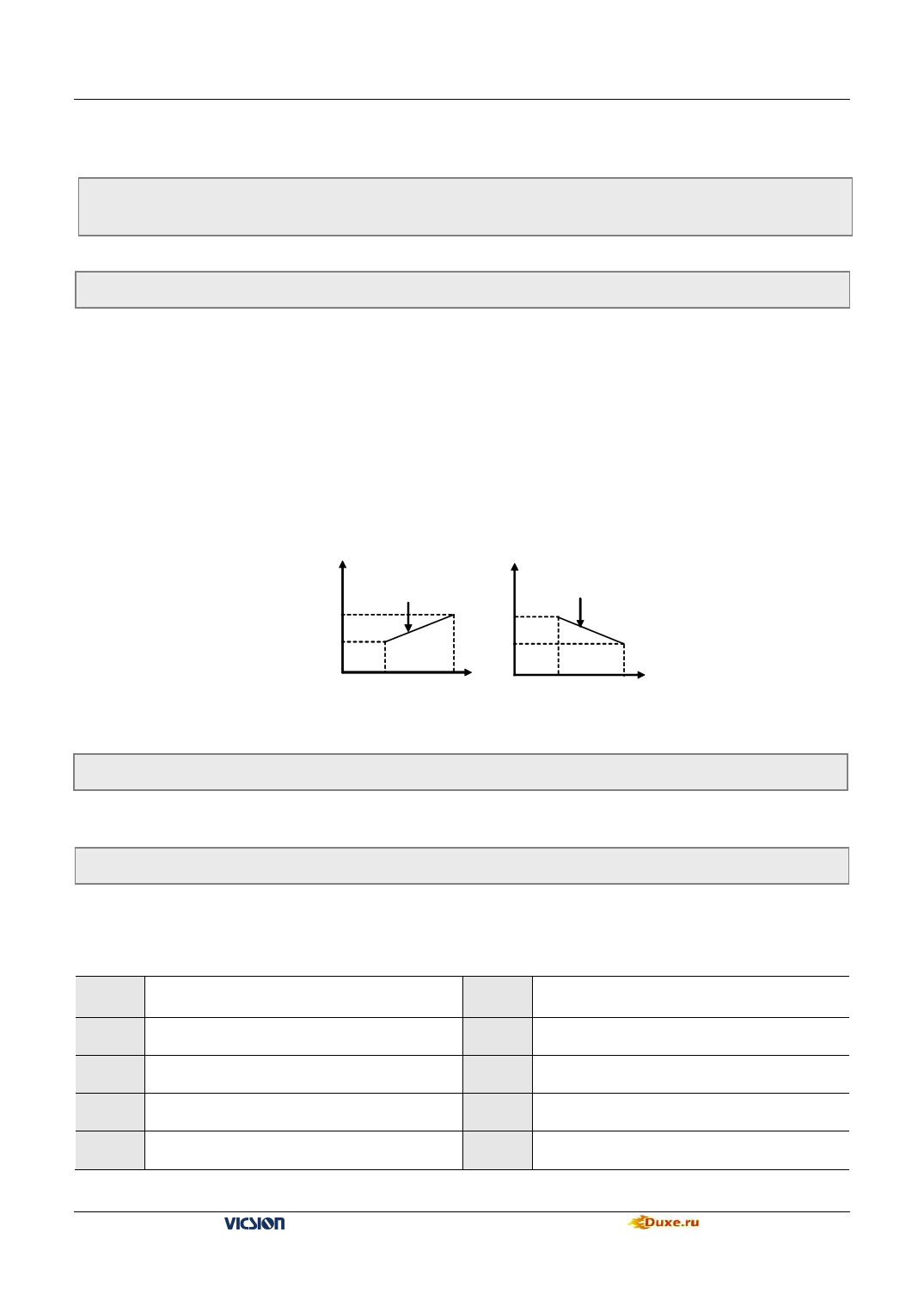
They define the Corresponding relation between analog input (pulse input) and setting frequency. Shown as fig.6-10
F2.10 Character selection of input channel
Setting channel: 0000 ~ 1111
It is used for selecting input character of external analog value or pulse value.
The first part of LED (form right to left): It defines character of voltage signal analog input VC1.
0: positive character
1:Negative character
The second part of LED (form right to left): It defines character of voltage signal analog input VC2.
0: positive character
1:Negative character
The third part of LED (form right to left): It defines character of current signal analog input CC.
0: positive character
1:Negative character
The fourth part of LED (form right to left): It defines character of pulse signal analog input PLS.
0: positive character
1:Negative character
The corresponding relation is shown as fig.6-10 between input signal and setting freq
Freq
[F2.9]
[F2.8]
Output freq
Freq
Output freq
[F2.9]
[F2.8]
Analog value Analog value
Input lower limit Input upper limi
Analog value Analog value
Input lower limit Input upper limi
Positive character
Negative character
Fig.6-10 Corresponding relation between analog input and setting freq
F2.11 External freq. set time constant of filtering
Setting range: 0.01 ~ 1.00s
Setting freq. set by external analog input will be filtered to eliminate fluctuation. Time constant of filtering have to
appropriate set according to fluctuate of external input signal.
F2.12 Combination setting mode
Setting range:0 ~ 29
The parameter is valid only when the frequency input channel F0.1 is set as 8
The setting frequency of the inverter is determined by the linear combination of multiple frequency input channels, and
please see the following table for the combination modes of setting. Frequency output of inverter jointly controlled by
multiple channels can be realized through the combination setting.
Setting
Value
Combination setting mode
Setting
Value
Combination setting mode
0
External voltageVC1 + External current CC
1
External voltageVC1 - External current CC
2
External voltageVC2 + External current CC
3
External voltageVC2 - External current CC
4
External voltageVC1 + External voltageVC2
5
External voltageVC1 - External voltage VC2
6
External voltageVC1 + pulse setting
7
External voltageVC1 - pulse setting
VS500 series of general purpose inverter Duxe.ru

