- You are here:
- AM.CO.ZABuythisCNC Utilities Homepage
- EasyRoute-CNC-Router
- Component Manuals
- VICSION VS500 Inverter Manual.pdf
- Page 54 of 113
50 VICSION VS500
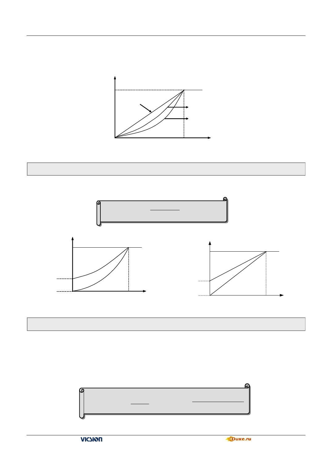
fan, pump, etc. If there is some unstable phenomenon in light-load running, please switch to run in the decreasing
torque curve 1.
3: V/F user-defined curve
It is used for setting user-defined curve which user need
Voltage
[F1.4]
The max
tput voltage
Constant torque curve
Decreasing torque
curve 1
Decreasing torque
curve 2
Fig. 6-4 V/F curve
[F1.3]
f
Basic running freq
F1.1 Torque Boost(output voltage at 0 Hz)
Setting range:0.0 ~ 20.0(%)
It is used for improving the low-frequency torque character. In low-frequency running, it will make boost
compensation for the output voltage of inverter, as shown in Fig.6-5.
Boost voltage =
[F1.1]
× [F1.4]
100
[F1.4]
Voltage
Voltage
[F1.4]
[F1.1]
Boost
voltage
f
[F1.3]
(1)Decreasing torque curve
Fig.6-5 Torque boost
F1.2 Torque boost pattern
[F1.1]
Boost
voltage
f
[F1.3]
(2)Constant torque curve
Setting range:0 ,1
0:Manual
Torque boost voltage is completely controlled by F1.1. There are two features: voltage will steady boost. And motor will
easily magnetic saturation when light-load.
1:Automatic
Torque boost voltage is changed with the stator current of motor. The boost voltage is higher with the stator current
higher.
Boost voltage = [F1.1] ×[F1.4]× Inverter’s output Current
200
2×inverter’s rated current
VS500 series of general purpose inverter Duxe.ru

