- You are here:
- AM.CO.ZABuythisCNC Utilities Homepage
- EasyRoute-CNC-Router
- Component Manuals
- VICSION VS500 Inverter Manual.pdf
- Page 51 of 113
Duxe.ru VICSION VS500 47
2:Three- line mode
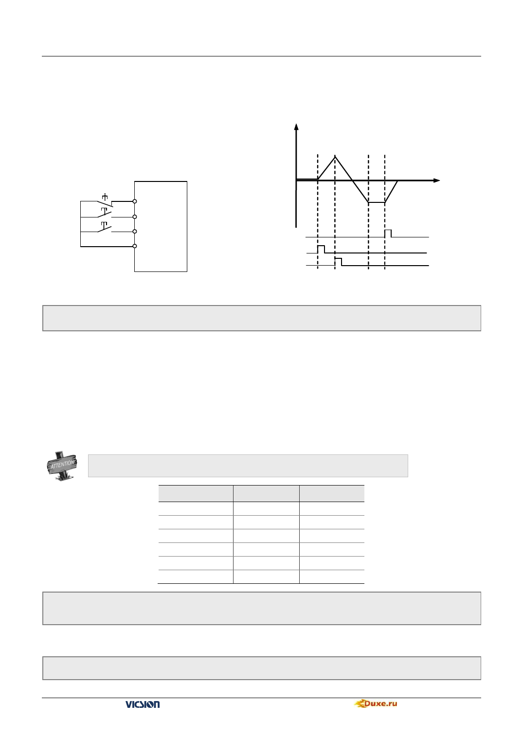
Please select a three-line mode terminal to set three-line mode. (Refer to description of parameters F3.0 ~ F3.5) X?is
three-line mode terminals,and it is any one among terminals X1 ~ X6
Switch function is shown as follow:
1. SW1 —— Stop trigger switch of inverter
2. SW2 —— FWD trigger switch
Output freq
3. SW3 —— REV trigger switch
SW1
SW2
SW3
X?
FWD
REV
CM
Fig.6-1 three-line mode wiring
t
SW1
SW2
SW3
Fig.6-2 output freq when three-line
F0. 6 Running direction control and instruction auxiliary setting
Setting range:0000 ~ 0111
It is used for changing the output phase-sequence of inverter, which changes the operating direction of motor (set by
binary system)
The third part of LED:External operation channel auxiliary function
0:Self-starting is forbidden when inverter is just power-on
1:Self-starting is allowed when inverter is just power-on
When [F0.6]=#0##,when inverter is just power-on,even though the control terminal is in running,the inverter will not
self-starting. In order to operate inverter, you should first give a stop signal, then a start-up instruction.
This parameter is used for modifying the present output phase sequence of inverter, which modifies the running
motor direction. Control effect of panel control method is shown as following table.
Parameter F0.4 is valid together with direction control of external terminals.
FWD-CM
OFF
ON
OFF
OFF
ON
ON
[F0.6]
# # 1 #
# # 1 #
# # 0 0
# # 0 1
# # 0 0
# # 0 1
Direction
FWD
FWD
FWD
REV
REV
FWD
F0.7 The lower limit frequency
F0.8 The upper limit frequency
Setting range:0.0 ~ [F0.8] Hz
Setting range:[F0.7] ~600.00Hz
When setting freq. is lower than lower limit freq., the inverter will run in lower limit freq. But the parameters
F4.8 and F4.9 are priority over F0.7 and F0.8.
F0.9 Reserved
VS500 series of general purpose inverter Duxe.ru

