- You are here:
- AM.CO.ZABuythisCNC Utilities Homepage
- EasyRoute-CNC-Router
- Component Manuals
- VICSION VS500 Inverter Manual.pdf
- Page 50 of 113
46 VICSION VS500
F0.4 Operation channel selection
Setting range: 0000 ~ 0012
It is used for selecting operation channel of inverter and function of key
.
The first part of LED (form right to left): to select operation channel of inverter.
0: Keypad control
The inverter is controlled by key
, ,
and on the keypad. And FWD state will affect output phase
sequence of inverter. When FWD is on with CM, output phase sequence will reverse with setting sequence,
contrariwise, output phase sequence will go the same way with setting sequence.
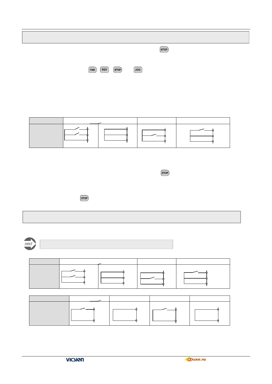
1: External terminals control
The inverter receives running instruction from external terminals FWD, REV and CM. The manufacture setting is
shown as follows.
Instruction
Terminals
State
STOP Instruction
FWD
REV
CM
FWD
REV
CM
FWD
FWD
REV
CM
REV
FWD
REV
CM
2: RS485 interface
Through serial communication, it receives instruction of setting frequency from PC or the master
The second part of LED (form right to left): to select function of the key.
0: It is valid for panel control.
When F0.4 is 0, Stop key on the operation panel is available.
1: It is valid for all kinds of control method.
When F0.4 is not 0 and press stop key, inverter will emergency stop and twinkling display Fu.16.
The third and fourth part of LED(form right to left):Reserved.
F0.5 Combination methods of instruction terminals
Setting range:0 ~ 2
It is used for setting control mode of external terminals.
This parameter will be valid only when F0.4 is set as ###1
0:Two-line mode 1 (default setting)
Instruction
STOP Instruction
Terminals
State
FWD
REV
CM
0:Two-line mode 2
Instruction
Terminals
State
STOP Instruction
FWD
CM
FWD
REV
CM
FWD
FWD
REV
CM
run
FWD
CM
FWD
REV
CM
REV
FWD
REV
CM
REV
REV
CM
VS500 series of general purpose inverter Duxe.ru

