- You are here:
- AM.CO.ZABuythisCNC Utilities Homepage
- EasyRoute-CNC-Router
- Component Manuals
- VICSION VS500 Inverter Manual.pdf
- Page 29 of 113
Duxe.ru VICSION VS500 25
4.4 Simple Operation
4.4.1. Initialization
(1)Frequency input channel / mode selection([F0.1])
Initialization of inverter is different according to different model. If [F0.0] is 0, the frequency of inverter is set by
keypad.
(2) Operation channel selection([F0.4])
Initialization of inverter is different according to different model. If F0.4 is 00#0, Start and stop of inverter is
controlled by
and
key.
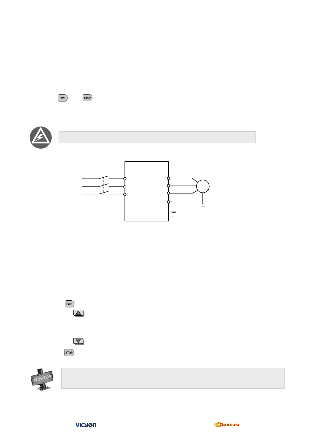
4.4.2. Simply operation
It is forbidden to connect Three-phase power to output terminal U, V and W directly.
Three-phase
Breaker
×
R
Power supply
×
S
×
T
Motor
U
V
M
W
E
Earth
Fig.4-1 simply running
①Please wire as the Fig 4-1.
②Be sure that the wiring is correct and turn the power on, the inverter will display “P.oFF” and”0”.
Auxiliary LED displays the program version transitorily.
③Be sure that F0.1 is 0.
④Please set parameters [F1.3] and [F1.4], according to the nameplate parameters of applied motor.
⑤Please press
⑥Please press
key to start inverter, then the inverter will display 0.0Hz.
key to increase input frequency and motor will run.
⑦Observe the motor whether it runs normally or not. If abnormal, please stop running at once and turn off the power,
and find out the reason, then restart.
⑧Press the key
to decrease the setting frequency.
⑨Press the key
to stop running. Then turn power supply off.
Carrier wave frequency is fixed value between 1.5 and 10 KHz. If motor does not take any load, it will a
slight oscillate. So please decrease setting value of F0.16, Or setting Oscillatory inhibiting factor value of
FC.11
VS500 series of general purpose inverter Duxe.ru

