- You are here:
- AM.CO.ZABuythisCNC Utilities Homepage
- EasyRoute-CNC-Router
- Component Manuals
- VICSION VS500 Inverter Manual.pdf
- Page 24 of 113
20 VICSION VS500
4. OPERATIONS OF INVERTER AND SIMPLE RUNNING
Operation panel has two functions:One is to modify the running state parameters. The other is to check and modify the
internal parameters. So operation panel has two modes: modify mode, check and modify parameters mode.
Usually, operation panel mode is in normal modify mode when inverter is just power-on. At this time, current running
parameter , which is shown on operation panel , is controlled by F6.12、F6.13. The operation panel mode will return the
normal modify mode, if there isn’t any operation on panel in 1 min.
4.1 Operation panel
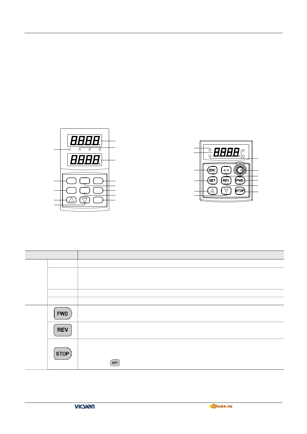
4.1.1 Panel layout
Mode indicate light
RUN
Hz
A
V
Main LED
U nit
Auxiliary LED
Return
Set
Increasing
Decreasing
ESC JOG <<
SET REV FWD
STOP
Switch
Jog
FWD
REV
Stop
Mode indicate light
RUN
Main LED
Hz
Return
Set
Increasing
Decreasing
V
A
Unit
Potentiometer
Switch
FED
REV
Stop
Fig.4-1-A Panel layout
Fig.4-1-B Small Panel layout
4.1.2 Function of Key
Item
Main LED
Display
Auxiliary
LED
Function
It displays current state and setting parameter.
It displays current state and setting parameter. At the beginning of power supply, it displays inverter’s
program version, and it will return normality in 2 second. Small panel layout doesn’t have this auxi liary
LED
A、Hz、V
RUN
The corresponding unit of current display.
Operation indicator light. The inverter is running and U, V and W output voltage.
FWD key:When F0.1 is 0 and press this key, the inverter will running forward to setting frequency according
to appointed ACC or DEC curve.
Keypad
REV key: When F0.1 is 1 and press this key, the inverter will be running backward to setting frequency
according to appointed ACC or DEC curve.
Stop and Reset key:
When F0.4 is 000#, STOP is valid for panel control. If F0.4 is 001#, STOP is valid for all kinds of
control methods. If inverter occur fault, press this key to reset it and return stop mode. If stop key is used
together with
copy and read-in of internal parameters will be done
VS500 series of general purpose inverter Duxe.ru

