- You are here:
- AM.CO.ZABuythisCNC Utilities Homepage
- EasyRoute-CNC-Router
- Component Manuals
- VICSION VS500 Inverter Manual.pdf
- Page 22 of 113
18 VICSION VS500
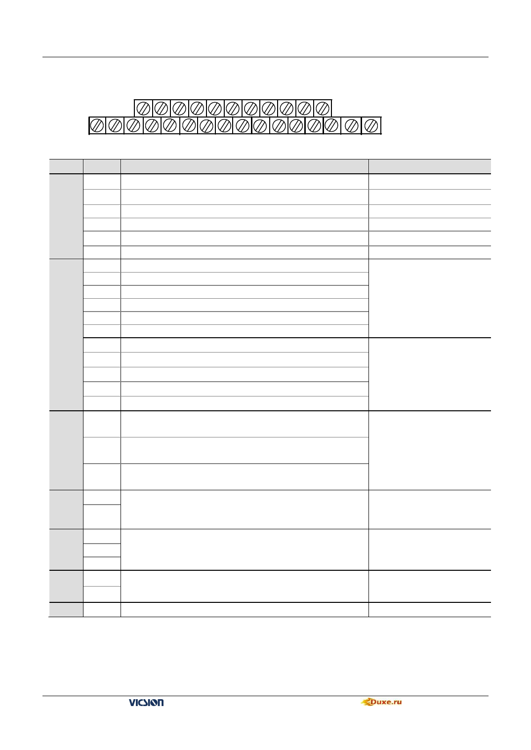
3.5 Terminal of Control circuit
X1 X3 X5 CM RST 24V OC2 PLS CC GND AO2
TA TB TC X2 X4 X6 FWD REV OC1 VS VC1 VC2 AO1 ERH + -
Type Terminal
Function
VS
It provides +10V/10mA or +5V/50mA power to JP1
VC1 Frequency setting voltage signal input terminal 1
Analog
Input
Control
Terminal
VC2
CC
PLS
GND
X1
X2
X3
X4
X5
X6
FWD
Frequency setting voltage signal input terminal 2
Frequency setting current signal input terminal
Pulse input signal terminal
Common terminal of Frequency setting voltage signal
Multi-function input terminal 1
Multi-function input terminal 2
Multi-function input terminal 3
Multi-function input terminal 4
Multi-function input terminal 5
Multi-function input terminal 6
FWD control command terminal
REV REV control command terminal
RST Fault reset input terminal
CM
Common terminal of control
24V
AO1
Analog
Output AO2
It provides +24V/50mA power and is grounded by CM.
PLC voltage signal input terminal1. It is set by F2.13 and allowed to
connect with external voltmeter.
PLC voltage signal input terminal 2. It is set by F2.14 and allowed to
connect with external voltmeter.
GND Common terminal of AM1and AM2
OC1
OC
Output
OC2
PLC open-circuit collector output is set by F3.6 and F3.7
TA
PLC
output
TB
TC
RS485
+
Interface
-
ERH
General , TA-TB is connected,TA-Tc is unconnected
when TA-TB is unconnected and TA-TC is connected,F3.8 is valid.
RS485 interface
Grounding terminal
Notes
Switch JP1
0~5V
0~10V
0~20mA
0~50KHz/5~30V
The detailed function of
multi-function Input terminal is
by set parameter F3.0~F3.5,
The terminal is valid while
being closed with CM
terminal.
Those terminals are valid
when it connects with CM.
And running direction of
panel control is controlled by
FWD-CM state
voltage signal output :
0~20mA/0~15V.
Voltage signal output :
0~10V/1mA
Switch JP2、JP3 select voltage
or current
The maximum load-current is
50mA, while the maximum
withstand voltage is 24V.
Capacity:AC 250V 1A
Resistive load
VS500 series of general purpose inverter Duxe.ru

