- You are here:
- AM.CO.ZABuythisCNC Utilities Homepage
- EasyRoute-CNC-Router
- Component Manuals
- VICSION VS500 Inverter Manual.pdf
- Page 17 of 113
Duxe.ru VICSION VS500 13
3. WIRING PROCEDURE
3.1 Precautions
3.1.1.
3.1.2.
3.1.3.
3.1.4.
3.1.5.
3.1.6.
3.1.7.
3.1.8.
Installing a middle breaker between inverter and power supply in order to avoid enlarging the accident.
Reducing the electromagnetic interference (EMI), please connect surge absorber to the coils of
electromagnetic contactors, relays, etc.
Frequency setting terminals (VC1, VC2, CC and PLS), Instrument circuit (AO1 and AO2), etc., these
analog signal wires should be over 0.3mm2 shield wire. Shield layer is connected with earth terminal
GND and the length of wire should be than 30m.
Wire of relay input and output circuit(X1 ~ X6、OC1、OC2、FWD、REV、RST) must be selected over
0.75mm2 shield wire. Shield layer should be connected to earth terminal CM and the length of wire should
be shorter than 50m.
Separating the main circuit wire from the signal/process circuit wiring,paralleled wiring should be at a
distance of over 10cm and crossed wiring should be vertical with each other.
The wire must be less than 30m between motor and inverter. When the length of wire is over 30m, the
carrier frequency of inverter should be reduced properly.
All of leading wires should be tightened with the terminal adequately to ensure well-contact. The leading
wire of main circuit had better use the cable or cuprum tier, and wiring had better be operated after the lug
plate of corresponding section’s cold pressing or welding.
Compressive resistance of all the wire should match with the voltage grade of inverter.
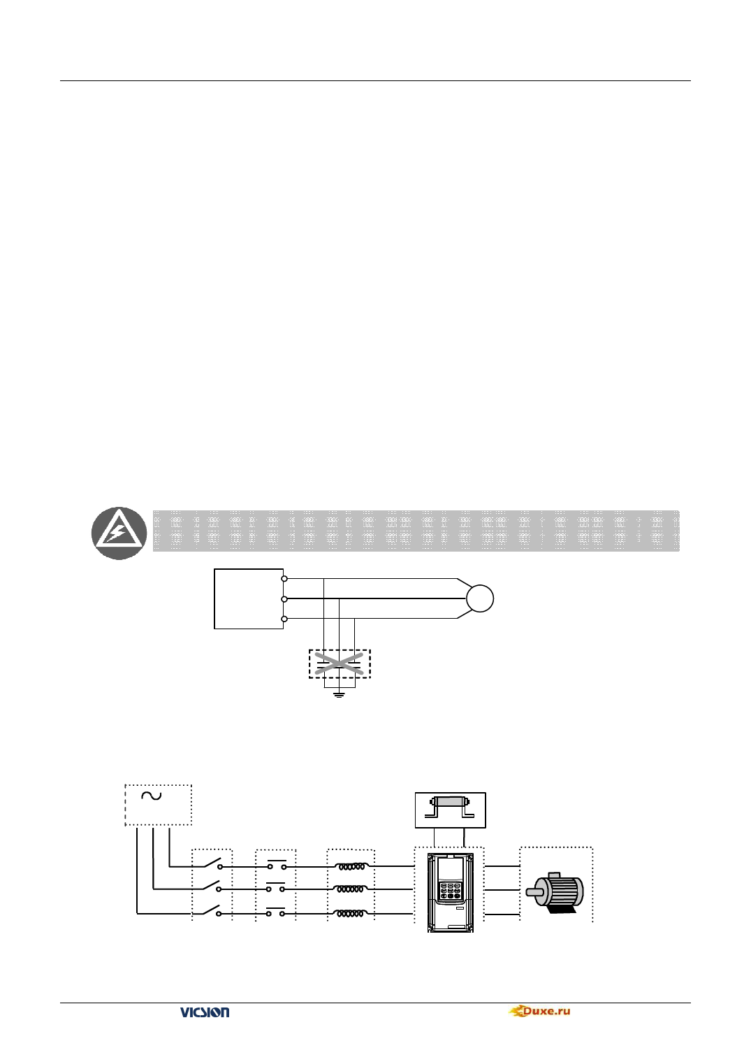
It is not allowed that U、V、W of inverter connect with the surge absorber capacitor or other surge absorber
equipment and shown as following Fig..
U
Inverter V
W
Motor
M
RC absorb
Fig 3-1 Output end prohibited from connecting with resistance-capacitance absorbing device
3.2 Wiring of External Components
Brake resistor
AC Power
Air Breaker Circuit
switch
Breaker
P+
R / L1
S / L2
T
PB
U
V
W
AC
Electric Breaker
VS500
Motor
Fig 3-2 Wiring of inverter
VS500 series of general purpose inverter Duxe.ru

