- You are here:
- AM.CO.ZABuythisCNC Utilities Homepage
- EasyRoute-CNC-Router
- Component Manuals
- VICSION VS500 Inverter Manual.pdf
- Page 111 of 113
Duxe.ru VICSION VS500 107
If the braking effect is not obvious, please decrease brake resistance and increase power of brake resistance according
to proportion.
The braking resistor power is the estimated value under the intermittent working of the braking
resistor. The power level of the braking resistor shall be appropriately increased when the braking
resistor continuously works for relatively long (over 5s), on the premise of the same resistance value.
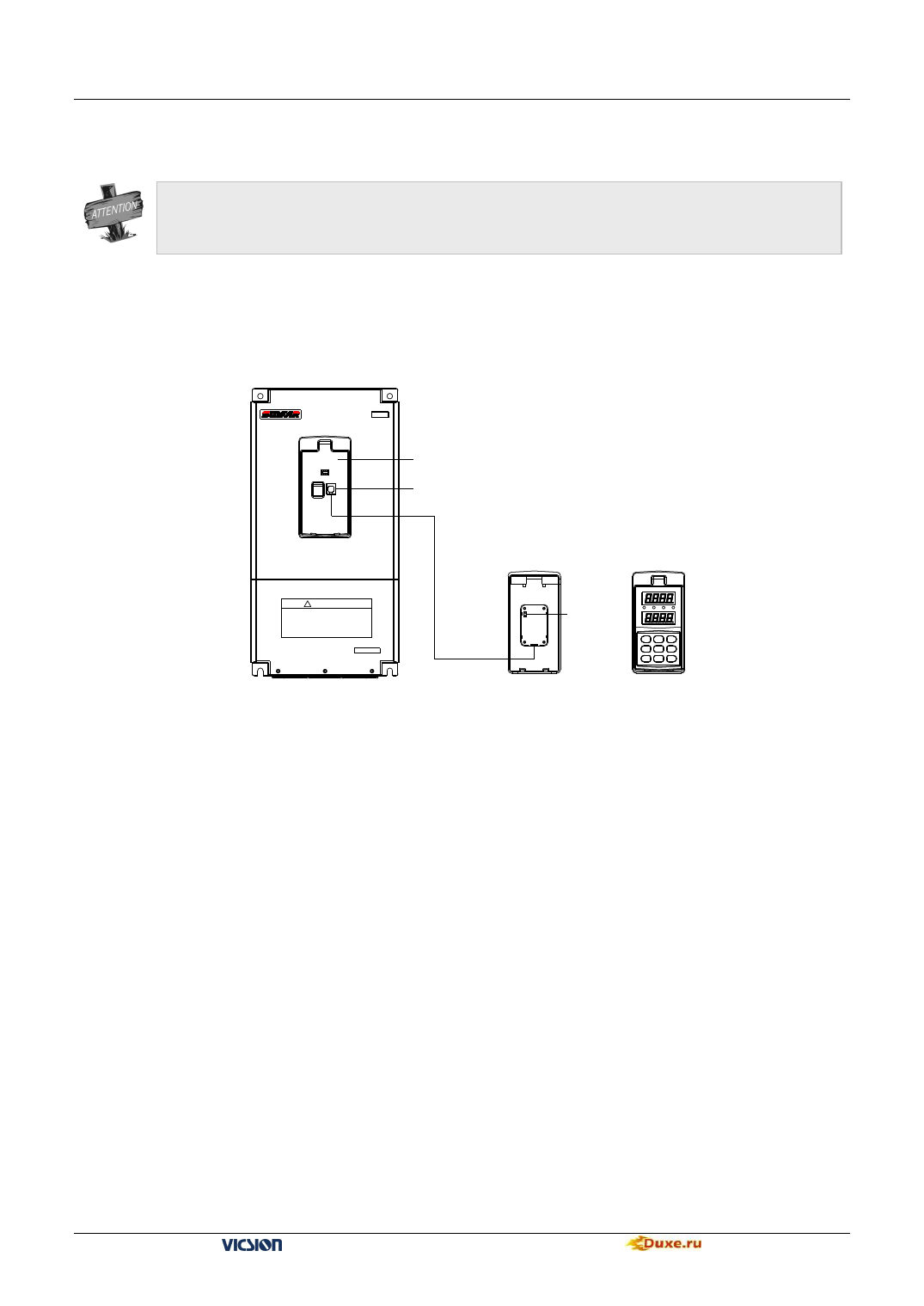
3. Remote Control Panel 1
3.1 Remote Control Panel Wiring Diagram
E380
Remote control panel sending base
RS485 (connecting with remote control panel receiving base)
! WARNING
1.Refer to the instruction manual before installation
and operation.
2.Do not connect AC pow er to output terminals UVW.
3.Do not remove any cover while applying power
and at least 10min. after disconnecting power.
4.Securely ground(earth) the equipment.
6-core
communication
cable
Connect to
DC24V
power source
Inverter
Remote control panel
receiving base back diagram
Fig. C-5 Remote Control Panel Wiring Diagram
Remote control
panel front diagram
3.2 Description of remote keyboard connection
1.Install the sending dock of the remote keyboard on the inverter, and install its receiving dock at the designation place
for operation, which communicates with the sending dock through the 6-core communication cable (connected
through RS485 interface).
2.The remote keyboard needs connecting with the external DC15-24V (18V recommended) for power supply.
4. Remote Control Panel 2 (RMKB001 Remote Control Panel)
4.1 Scope of application
RMKB001 type remote control panel applies to the remote control and operation of the E320, E380 and C300 series
variable frequency speed controllers produced by Shenzhen Sunfar Electric Technologies Co., Ltd.
This remote control panel can be used at the same time with the operation panel of the inverter, and the viewing,
modification and storage of parameters are valid at the same time.
RMKB001 remote control panel requires the independent 10-24 DC power supply. The 24V DC power supply of
terminal of the inverter can be selected when the remote control wiring length is <100m and impedance is <50Ω (refer
to the basic wiring diagrams C-6 and C-7).
VS500 series of general purpose inverter Duxe.ru

