- You are here:
- AM.CO.ZABuythisCNC Utilities Homepage
- EasyRoute-CNC-Router
- Component Manuals
- VICSION VS500 Inverter Manual.pdf
- Page 102 of 113
98 VICSION VS500
10. 5 Energy-saving reconstruction of escalator (for reference only)
10.5.1 Initial setting
1. Command channel: External control ([F0.4] =###1).
2. Mode of running command: 3-wire mode ([F0.5] =2).
3. 3-wire running control: Select the terminal X3 ([F3.2] =18).
4. Relay output selection: Time of internal timer is up ([F3.8] =11).
5. Internal timer: be set according to the specific circumstance ([F6.0]).
6. Trigger terminal of internal timer: Terminal X4 ([F3.3] =24).
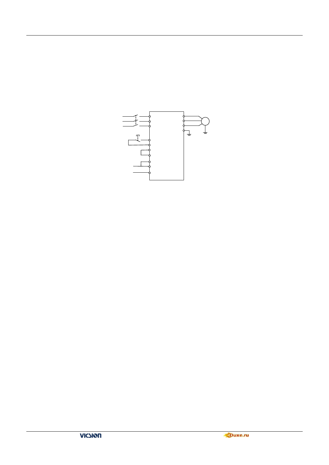
10.5.2 Basic Wiring Diagram:
Three phase breaker
Three phase
power supply
×
R
×
S
×
T
motor
U
V
M
W
E
Infrared sensor input
(valid while on)
X3
TA
TB
CM
X4
FWD
CM
Fig. 10-5 Basic Wiring Diagram
10.5.3 Operation instructions
Under the normal state, when TA and TB are connected, X3 and CM will be naturally connected to form the valid
command status. At this time, when there is input signal by infrared induction, FWD terminal will receive the starting
signal for running and the inverter will start to run. After running to the time set by parameter [F6.0], TA and TB will
output 0.5s disconnection signal and the inverter will stop running.
This scheme is used in inductive self-running control of the escalator: the escalator automatically stops when there is
no person and logistics (it is used only in the reconstruction of the escalator that can be stopped).
10.6 PLC control of start/Stop and 3-stage speed running of inverter
10.6.1 Introduction of exemplificative control function:
One typical control method is hereby provided through one simple routine of PLC control of inverter, to achieve the
purpose of integrating the inverter and the system. The control approach is as follows: 1. Start inverter running through
X0 terminal; 2. Stop inverter running through X5 terminal; 3. Connect X1, X2, and X3 to separately correspondingly
output frequencies 10Hz, 20Hz and 50Hz; 4. When terminals are connected at the same time, the frequency output is
invalid (outputting 0 frequency).
10.6.2 System configuration:
Master station: Mitsubishi PLC Model: FX2N-16MR-001
Slave station: E380-4T0220 series inverter
10.6.3 Hardware connection of the master and slave
SUNFAR inverter can realize RS485 communication with PLC by connecting with crystal head telephone line, show
as follows:
VS500 series of general purpose inverter Duxe.ru


