Functional Details 57
Figure 6-13 Sketch of acceleration torque and braking torque
F2.07 Motor overload protecting coefficient Setting range: 50 ~ 110 (%)
This parameter is used to set inverter’s sensitivity of thermal relay protection for
load motor. When the rated current of the load motor is not matching with the
inverter’s rated current, it is applicable to set this value to provide correct
thermal protection over the motor. When it is set to 110%, the inverter will
disable the motor overload protection function.
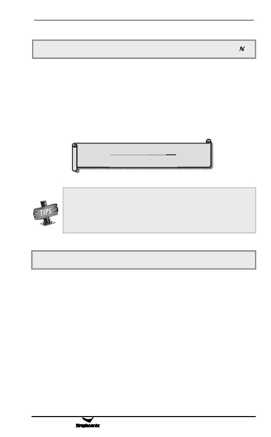
The set value of this parameter is determined by following formula.
电Mo机tor额ra定ted电c流urrent
[F2.07]= Inv变er频 ter器ra额 ted定ou输tpo出ur电cu流rrent×100%
When one inverter and multiple motors run in parallel, the
inverter’s thermal relay protection function will be disabled. In
order to effectively protect motors, it is suggested to install a
thermal protecting relay at the inlet wire terminal for each motor.
F2.08 Dynamic braking initial voltage Setting range: 300~400V/600~800V
This parameter is effective for inverters with built-in braking unit and is used to
define action parameters of inverter’s built-in braking unit. When the inverter’s
internal DC side voltage is higher than dynamic braking initial voltage, the
built-in braking unit acts. If external braking resistor is connected, the inverter’s
internal DC side pumping voltage energy will be released through the braking
resistor so as to reduce the DC voltage. When the DC side voltage reduces to
certain value ([F2.08]-50V), the inverter’s built-in braking unit is closed, as
shown in Figure 6-14.
E500 Series Universal Low-Power Inverter

