20 Function Parameter Table
4 Operating Panel
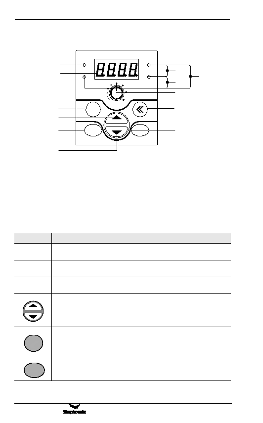
Runnin运g行in指dic示at灯or
Digit数al码di显sp示lay
R返etu回rn
上 U升P
S设ettin置g
RUN
Hz
MIN
ESC
SET
V
A
MAX
RUN
STOP
数D码igi显tal示d数isp据la单y d位ata unit
sec
%
rmp
P面a板ne电l p位ot器entiometer
S移hi位ft
R运u行n,、st停op止, r、est复or位e
D下ow降n
Figure 4-1 Operating Panel Sketch
Note: E500 series keyboard port can be compatible with SIMPHOENIX
E300 and E310 series, and other series keyboard is not compatible. Do not
make confusion.
4.1 Function description of keys
Keys
Digital
display
A, Hz, V
RUN
ESC
SET
Function Description
Display the current operating status parameters and setting parameters of
the frequency inverter.
Display the measurement unit corresponding to the main digital display
data.
Operating indicator, indicating the inverter is running, and there is output
voltage at the output terminals U, V and W.
Data modification key. It is used to modify functional code or parameters.
At the status monitoring mode, if the frequency command channel is at
the digital setting mode ([F0.00]=0), press this key to directly modify the
frequency set value.
Back key. At the normal monitoring mode, press this key to enter the
non-normal monitoring mode/monitoring parameter inquiry mode to see
the operating status parameters of the inverter. At any other operating
status, separately press this key to back to the previous status.
Set key. Confirm the current status or parameter (parameters are stored in
the internal memorizer) and enter the next function menu.
E500 Series Universal Low-Power Inverter


