2 Product Introduction
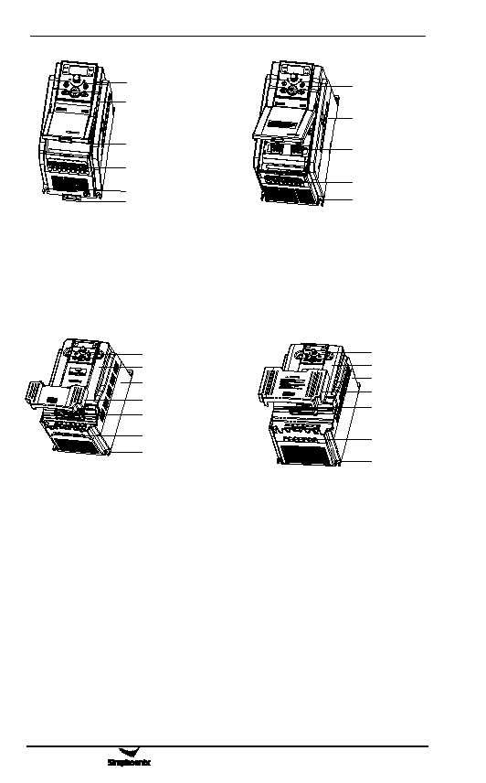
Operating panel
Housing
Control loop cable inlet
Main loop cable inlet
Bottom installation hole
Bottom guide rail fastener
Operating panel
Housing
Control loop cable inlet
Main loop cable inlet
Bottom installation hole
Figure 1-2 Appearance and Component
Name of Category Ⅱ Inverters
Applicable models:
E500-2S0015(B)~E500-2S0022(B)/
E500-4T0007(B)~E500-4T0022(B)
Figure 1-3 Appearance and Component
Name of Category III Inverters
Applicable models:
E500-2S0030(B)~E500-2S0040(B)/
E500-4T0030(B)~E500-4T0040(B)
Operaing panel
Upper shell
Lower shell
Lower looer
Control loop cable inlet
M ain loop cable inlet
Bottom installation hole
Operaing panel
Upper shell
Lower shell
Lower looer
Control loop cable inlet
Main loop cable inlet
Bottom installation hole
Figure 1-4 Appearance and Component
Name of Category IV Inverters
Applicable models:
E500-4T0055~E500-4T0075/
E500-2S0055
Figure 1-4 Appearance and Component
Name of Category V Inverters
Applicable models:
E500-2S0075/
E500-4T0090
1.4 Product technical indicators and specifications
Power range of E500 series: E500-2S0007~ E500-2S0075/E500-4T007~
E500-4T0090。
Technical index and typical function of E500 series
E500 Series Universal Low-Power Inverter

