4.2 Position control mode
4.2.4 Gains related to position control mode
Param
eter
P009
P021
P022
Name
gain of position loop
Feed forward gain of position loop
Time-constant of feed forward filter
for position loop
Range
1~1000
0~100
0.20~50.00
Default
Unit Usage
value
40
1/s
P
0
%
P
1.00 ms
P
According to the inner loop adjusts first and then the outer loop, the speed loop is included in the position
loop, therefore the rotation inertia ratio of load will be set first with suitable value. Then, the gain and the integral
time-constant of the speed loop are adjusted. At last, the gain of the position loop is adjusted.
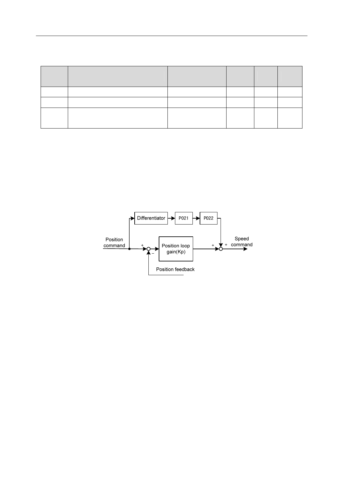
The following block diagram is the position regulator of the system. Increasing the gain of position loop can
get higher position loop bandwidth, but it is limited by the speed loop bandwidth. Therefore, in order to increase
the gain of the position loop must increase the bandwidth of speed loop first.
The feed forward can reduce the lagging of phase in the position loop; also reduce the position tracking error
as well as shorter positioning time. The feed forward quantity increases, the position tracking error reduces, but
can cause the system unstable and overshoot if the feed forward quantity is too large. If the electronic gear ratio is
more than 10 it is also easy to make noise. For normal application, the parameter P021 is set as 0%. If higher
response and lower tracking error are required, the P021 can be increased properly, but not in excess of 80%.
Meanwhile it may need to adjust the filter time constant (parameter P022) of the feed forward branch.
45
