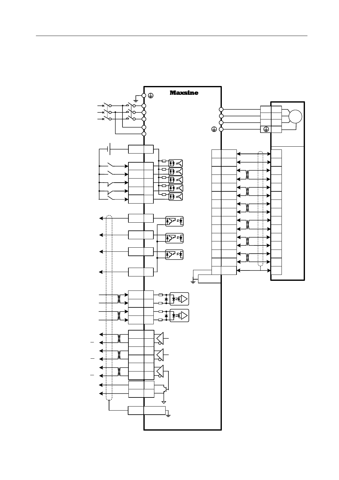
2.4 Standard wiring diagram
2.4.1 Wiring diagram for position control
2.4 Standard wiring diagram
3 Phase
AC 220V
QF
DC
12~24V
Servo On(SON)
Alarm Clear(ARST)
CCW Drive Inhibition(CCWL)
CW Drive Inhibition(CWL)
Position Deviation Clear(CLR)
Servo Ready(RDY)
Servo Alarm(ALM)
Electromagnetic Brake(BRK)
DO Common Terminal
Position Command(PULS)
Position Command(SIGN)
A
A
Encoder B
Signal
Outputs B
Z
Z
Z Signal Open-collector
Output
Encoder Signal Ground
EP1 Servo Drive
L1
L2
TL08F/TL12F/TL16F
U
L3
V
KM
W
L1C
L2C
COM+
X1
1
4.7kΩ
DI 1 14
DI 2 2
DI 3 15
DI 4 3
DI 5 16
DO 1
X1
4
X2
13
14
5
10
4
9
26LS32
3
Receiver 8
2
7
DO 2 17
1
6
DO 3 5
12
11
DO
COM
18
PULS+
PULS-
SIGN+
SIGN-
X1
110Ω
20
110Ω
7
110Ω
19
110Ω
6
15
X2 Metal
Case
OA+
OA-
OB+
OB-
OZ+
OZ-
X1
11
23
12
24
13
25
A
B 26LS31
Driver
Z
CZ
GND
FG
22
10
X1 Metal
Case
Signal Ground
Huada
Servomotor
U2
V3
W4
1
4 Cores Power
Connector
5V
2
0V
3
A+
4
A-
7
B+
5
B-
8
Z+
6
Optical
Z-
9 Encoder
15 Cores
U+
10 Connector
U-
13
V+
11
V-
14
W+
12
W-
15
FG
1
Note:
The DI and DO terminals
have Multi-functions
programmed by
software. Their default
settings shown in picture
can use for common
purposes. User can
modify it according to
different needs.
19


