Chapter 2 Wiring
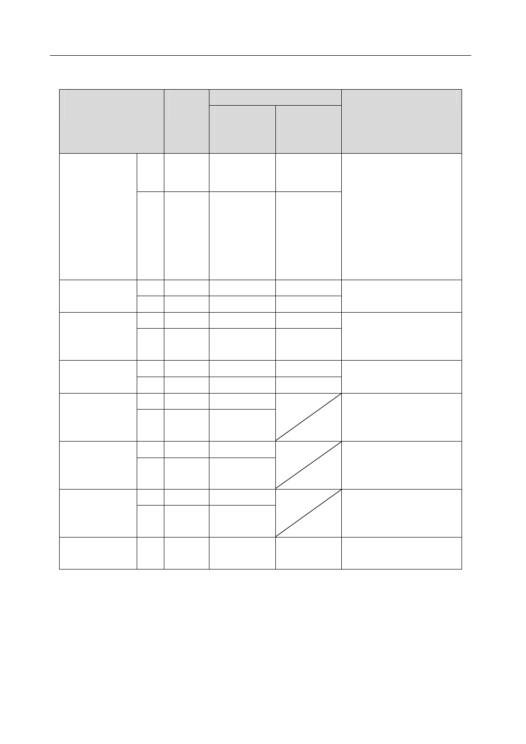
2.3.2 X2 terminal signal explanation
Signal name of
Pin
Colour of wire
Functions
encoder
number standard Wire saving
(16core)
(10core)
[note1]
[note2]
Power supply
5V 13
red+red
red+red Use 5VDC power supply
/white
/white
(provided by servo driver).If
the cable is longer than 20m,
0V 14 black+black black+black
in order to prevent encoder
/white
/white
from voltage drop down, it is
better to use multi wire or
thick wire for power line and
ground line.
A phase input
A+
5
brown
brown
Connect with A phase output
A- 10 Brown/white Brown/white of encoder.
B phase input
B+ 4
yellow
yellow
Connect with B phase output
B-
9
Yellow
Yellow of encoder.
/white
/white
Z phase input
Z+ 3
green
green
Connect with Z phase output
Z-
8
Green/white Green/white of encoder.
U phase input
U+
2
purple
Connect with U phase output
U- 7
Purple
of encoder.
/white
Not connect for wire saving.
V phase input
V+
1
blue
Connect with V phase output
V-
6
Blue/white
of encoder.
Not connect for wire saving.
W phase input
W+ 12
orange
Connect with W phase output
W- 11
Orange
of encoder.
/white
Not connect for wire saving.
Shield ground
FG 15
Bare wire Bare wire Connect with cable shield
wire.
Note: The optional extras provided by maxsine:
1. 16 core cable for the type of 16FMB15.
2. 10 core cable for the type of 10FBM15X (for using in the 80 frame of servomotor) and of 10FBM15 (for
using in the 110 and above frame of servomotor).
18


