Chapter 2 Wiring
2.2 X1 terminals for control signals
The X1 connector DB25 plug provides the signals interfaced with the host-controller. The signal includes:
z Five programmable inputs;
z Three programmable outputs;
z Analog command inputs;
z Pulse command inputs;
z Encoder signal outputs.
2.2.1 X1 terminal connector
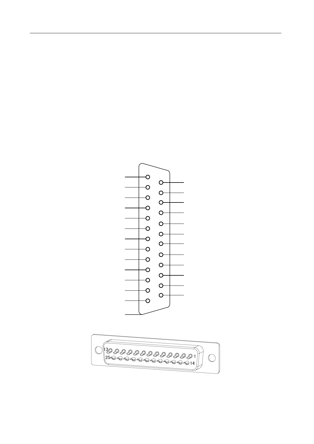
The X1 connector plug uses DB25 male head, the contour and pin disposition charts are as the followings:
DI Power Supply(COM+) 1
Digital Input 2 (DI2) 2
Digital Input 4 (DI4) 3
Digital Output 1 (DO1) 4
Digital Output 3 (DO3) 5
Position Command Direction -(SIGN-) 6
Position Command Pulse -(PULS-) 7
Analog Command Input -(AS-) 8
Analog Signal Ground(AGND) 9
Encoder Signal Ground(GND) 10
Encoder Signal A Output(OA+) 11
Encoder Signal B Output(OB+) 12
Encoder Signal Z Output(OZ+) 13
14 Digital Input 1 (DI1)
15 Digital Input 3 (DI3)
16
Digital Input 5 (DI5)
17
Digital Output 2 (DO2)
18 DO Common Terminal(DOCOM)
19 Position Command Direction +(SIGN+)
20
Position Command Pulse +(PULS+)
21 Analog Command Input +(AS+)
22 Z Signal Open-collector Output(CZ)
23 Encoder Signal /A Output(OA-)
24 Encoder Signal /B Output(OB-)
25
Encoder Signal /Z Output(OZ-)
Shield Protection Ground
(Connector case)
Servo Drive X1 Connector
Connector X1 Soldering Lug Disposition
10


