- You are here:
- AM.CO.ZABuythisCNC Utilities Homepage
- EasyRoute-CNC-Router
- Component Manuals
- HSD Spindle Instructions for Use.pdf
- Page 164 of 183
HSD
8.8.10
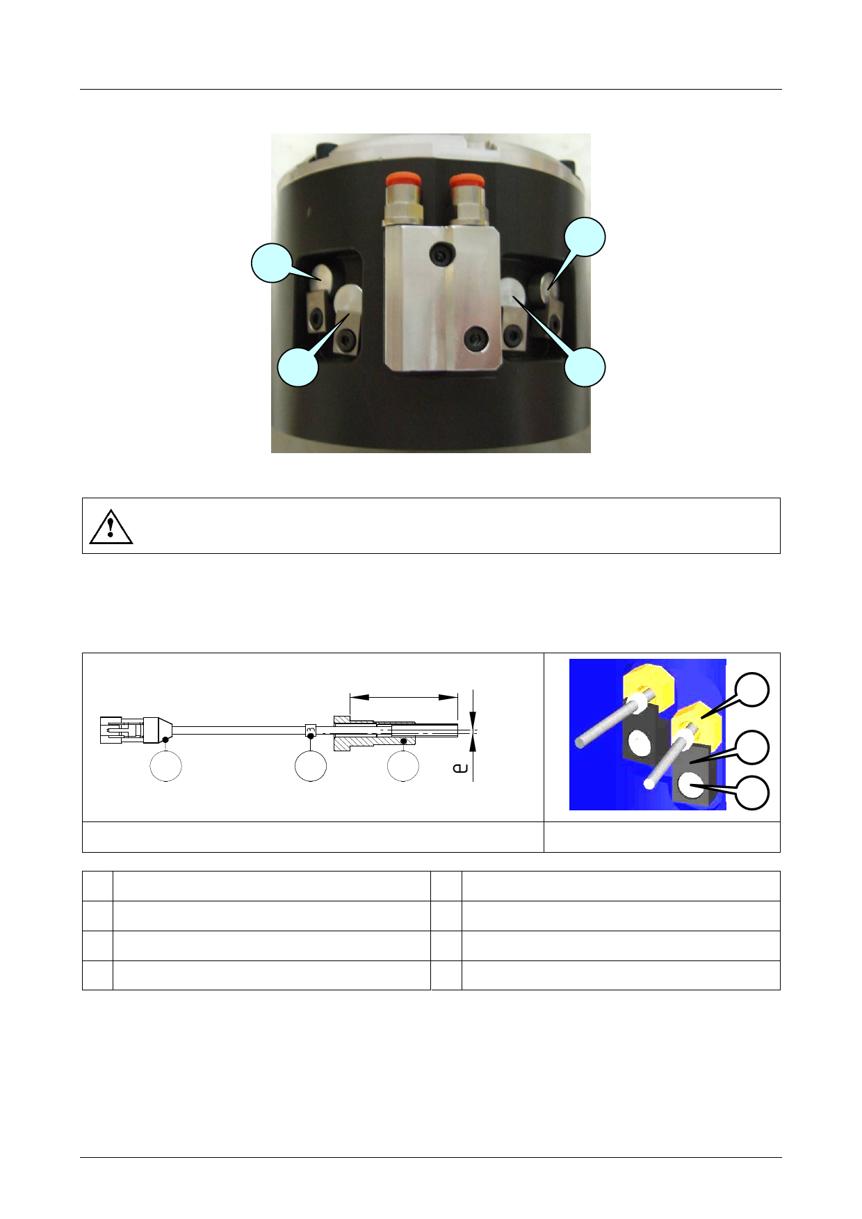
Position of the sensors in models ES884/ES888
S2
S3
S1
S4
8.8.11
Description of the sensor unit
The various sensors are identified by the number shown on the cable marking
label;
danger of damage to moving parts if sensors are swapped over.
The sensors are pre-assembled in calibrated bushes to allow simple insertion to the right depth in
the electrospindle.
It is therefore important to correctly identify the sensor to be replaced: for this reason, both the
sensors installed on the electrospindle and those supplied as spare parts bear a numbered cable
marking hose clamp (812).
L
4
1
2
3
Figure 812.sensor unit
5
6
Figure8 13.
1 Electrical connector
2 Cable marking label
3 Bush and sensor
L Calibrated position
E Eccentricity for adjustment
4 Sensor
5 Sensor blocking bracket
6 Embedded hexagon screw
5801H0056 ______________________________________________________________ 164/183

