Table of Contents
Important Safety Information.................................................................................................................................1
Chapter I Installation............................................................................................................................................ 3
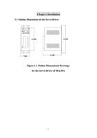
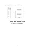
Outline Dimensions of the Servo Driver........................................................................................................... 3
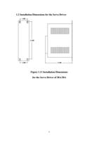
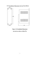
Installation Dimensions for the Servo Driver...................................................................................................... 4
Installation Site.................................................................................................................................................... 5
Direction and Space of Installation.....................................................................................................................6
Chapter II Overview of Functions.......................................................................................................................9
Basic Functions of MG -1000 Series of Servos............................................................................................ 9
Type Selection of the Servo Driver..................................................................................................................10
Chapter III Wiring..............................................................................................................................................13
Noti ces.................................................................................................................................................................13
Wiring Requirements..........................................................................................................................................13
Wiring Methods................................................................................................................................................. 13
Typical Wiring................................................................................................................................................... 14
Position Control (pulse type).........................................................................................................................14
Speed Control (analog value)........................................................................................................................ 15
Torque Control (analog value)....................................................................................................................... 16
Wiring Diagram for Wire Saving Motor Encoder................................................................................................. 17
Wiring Diagram for the Band-type Brake of the Servo Motor.....................................................................18
Chapter IV Interfaces..........................................................................................................................................19
Definitions of Servo Control Power Supply and Heavy Current Terminal.................................................19
Definitions of CN1 Interface and Control Signal Input/output..................................................................20
Definitions of CN2 interface and Encoder Input Signal.............................................................................. 25
Principle of the Input Interface for Switching Value.............................................................................................. 26
4.5 Principle of the Output Interface for Switching Value...............................................…............................. 26
4.6 Principle of the Input Interface for Pulse Value...........................................................................................27
4.6.1 Input Mode of Pulse................................................................................................................................. 28
Principe of the input interface of Analog Value............................................................................................28
Principe of Encoder Interface..........................................................................................................................30
CN1 Output Interface for Encoder Signal (from the driver to the upper computer)..............................................30
CN2 Input Interface for Encoder Signal (from the servo motor to the driver)........................................................ 31
CN1 Output Interface for Z signal of the Encoder (from driver output to zeroing by the upper computer) ...31
Chapter V Display and Operation...................................................................................................................... 33
Operation Panel................................................................................................................................................. 33
Components of Parameter Structure.................................................................................................................. 34
Status Monitoring Mode (DP - -)................................................................................................................. 35
Parameter Modification Mode (PA--)............................................................................................................ 38
Parameter Management Mode (EE--).............................................................................................................39
JOG Operational Mode (Jr- -)....................................................................................................................40
Speed Trial Run Mode (Sr- -).................................................................................................................... 40
Automatic Zeroing Mode of Analog Value (AU- -)......................................................................................41
Automatic Zeroing Mode of Encoder (CO- -)............................................................................................. 42
Open Loop Operation Mode (OL- -)............................................................................................................ 42
2

