
address machine.
4.2 Layer processing
First, in the menu 【Handle】->【Path optimize】 check “according to layer order”, then click
“OK” to exit.
Layer reorder: Click button Up, Down can change the order of layers, or direct the mouse to
drag the layer to the specified location.
Here, you must check the “Path optimize” option.
4.3 Position
Setting the laser head back location after processing completed.(Current position 、 Original
anchor、Machine Zero.
Current Position : Laser head back to the position before processing.
Original anchor : Laser head back to the last anchor ,the anchor may set at panel.
Machine zero : Laser head back to the zero of the machine.
4.4 Go Scale、Cut Scale
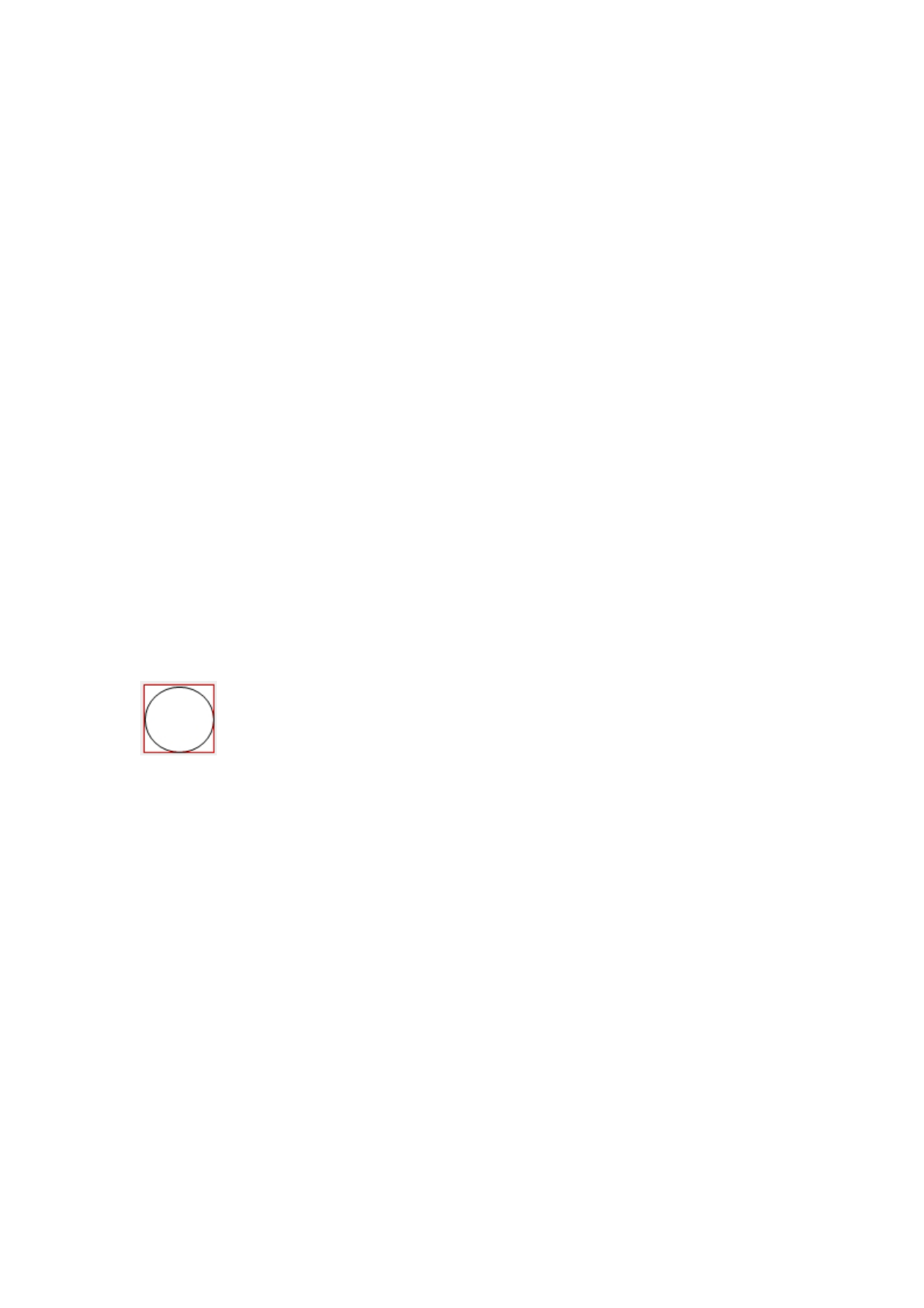
For Example Go Scale, As the following figure shown, the actual graphic is round, and the red
rectangle outside the circle is the smallest rectangle, click button Go Scale, laser head will run
once along the rectangular path.
For Example Cut Scale, As the following figure shown, the actual graphic is round, and the red
rectangle outside the circle is the smallest rectangle, click button Cut Scale, laser head will be cut
along the rectangle.
4.5 Start、Pause、Stop、Save To Un File、Un File Output、Download
Start:Output the current graphic to the machine for processing.
Pause\Continue:Click Pause,will stop the processing work , click the button again to Continue
Stop:Stop the current processing work
Save To Un File:
Save current file as RD format,using for offline processing(Can be copied to other memory board
for full offline operation)。
Un File Output:
Output the offline file (RD format)
 RDCAM V8.0 User Manual")
 RDCAM V8.0 User Manual")
 RDCAM V8.0 User Manual")
 RDCAM V8.0 User Manual")
 RDCAM V8.0 User Manual")
 RDCAM V8.0 User Manual")
 RDCAM V8.0 User Manual")
 RDCAM V8.0 User Manual")
 RDCAM V8.0 User Manual")