Page 69 of 100
Functional Details 62
F4.04 Communication overtime detection time Setting range: 0.1 ~ 10.0 Sec
When this inverter has not received correct data signal beyond the interval defined
by this parameter, it is judged that the inverter has subject to communication failure.
Then, it is appliciable to select shutdown or continuing running according to the
work mode after communication failure set by [F4.03].
F4.05 Linkage setting ratio
Setting range: 0.1 ~ 10.0
This parameter defines the ratio of main machine and slave machine output
frequency at the mode of linkage control.
This group parameter of the main inverter does not function. When linkage
synchronous control trough RS485 port is achieved, the running command of the
slave inverter is completely synchronous with the main machine. The frequency
command of the slave machine is calculated according to following method:
Slave inverter frequency command = Main inverter frequency command × [F4.05]
6.6 PID parameter group
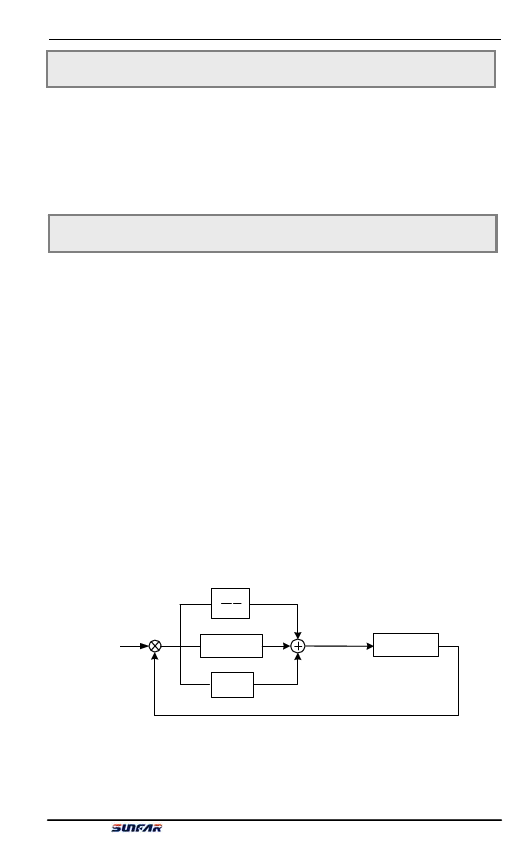
PID control is subject to calculation of ratio, integral and differential according to
the difference between the feedback value the controlled system and the target value,
so as to adjust the inverter’s output frequency and maintain the controlled system
stable with the target signals. The principle is shown in Figure 6-18.
??? +
Target value
-
Feedback?va?lue?
11
Ti S
Td*S+1
P
?Cos?ynstrt?oemlle?d
Figure 6-18 PID Function Sketch
E550 Series Universal Low-Power Inverter

