Functional Details 51
F2.08 Dynamic braking initial voltage Setting range: 300~400V/600~800V
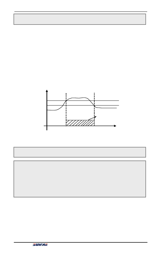
This parameter is effective for inverters with built-in braking unit and is used to
define action parameters of inverter’s built-in braking unit. When the inverter’s
internal DC side voltage is higher than dynamic braking initial voltage, the built-in
braking unit acts. If external braking resistor is connected, the inverter’s internal
DC side pumping voltage energy will be released through the braking resistor so as
to reduce the DC voltage. When the DC side voltage reduces to certain value
([F2.08]-50V), the inverter’s built-in braking unit is closed, as shown in Figure
6-14.
DC side vo直lta流g侧e
电压
[F2[F.20.808]]
[F2[.F028.0]-85]-050VV
制Br动ak单in元g动un作it action
Figure 6-14 Dynamic Braking
T时im间e
F2.09 ~ F2.10 Reserve
F2.11
F2.12
F2.13
F2.14
F2.15
F2.16
V/F frequency 1
V/F voltage 1
V/F frequency 2
V/F voltage 2
V/F frequency 3
V/F voltage 3
Setting range: 0.0~[F2.13]
Setting range: 0.0~[F2.14]
Setting range: [F2.11]~[F2.15]
Setting range: [F2.12]~[F2.16]
Setting range: [F2.13]~[F0.12]
Setting range: [F2.14]~[F0.13]
This functional parameter group is used to flexibly set user desired V/F curve. See
figure 6-15.
E550 Series Universal Low-Power Inverter

