Functional Details 50
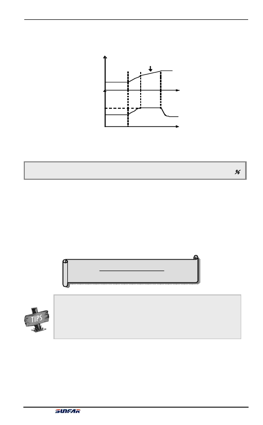
Therefore, if the acceleration time is required to be shorter, acceleration torque
level needs to be increased.
Freq频uen率cy
加Acc速elera时tion间tim调e ad整justment
Accelera加tio速n t力orq矩ue
[ F [2F2..0066] ]
时Tim间e
时Tim间e
Figure 6-13 Sketch of acceleration torque and braking torque
F2.07 Motor overload protecting coefficient Setting range: 50 ~ 110 (%)
This parameter is used to set inverter’s sensitivity of thermal relay protection for
load motor. When the rated current of the load motor is not matching with the
inverter’s rated current, it is applicable to set this value to provide correct thermal
protection over the motor. When it is set to 110%, the inverter will disable the
motor overload protection function.
The set value of this parameter is determined by following formula.
电Mo机tor额ra定ted电cu流rrent
[ F2.07]= Inv变ert频er 器rat额ed 定ou输tpo出ur 电cu流rrent× 100%
When one inverter and multiple motors run in parallel, the
inverter’s thermal relay protection function will be disabled. In
order to effectively protect motors, it is suggested to install a
thermal protecting relay at the inlet wire terminal for each motor.
E550 Series Universal Low-Power Inverter

