U
变Inv频ert器er V
W
Inverter Wiring 10
电M动oto机r
M
阻RC容a吸bso收rb装er 置
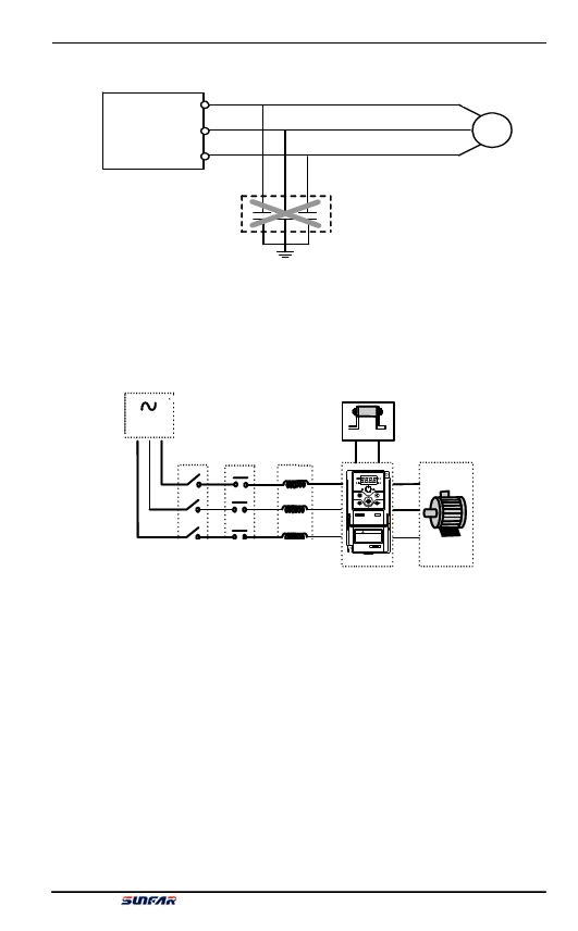
Figure 3-1 Forbidding connecting a RC absorber at the output terminal
3.2 Wiring of peripheral elements
Bra制ki动ng电r阻esistor
ACAsuCp电Ppoly源wer
PP
R/L1
PB
U
S/L2
T
Air switch Contactor AC reactor
空气开关 接触器 AC 电抗器
E550
! WARNING
1.R efer to the instructi on manual be fore ins ta llation
a nd ope rati on.
2.D o not conne ct AC pow er to output termina lsU VW.
3.D o not remove a ny cove r w hil e appl ying power
a nd at le as t1 0min. af te r dis conne cting pow er.
4.Se curel y gr ound(e arth) the equi pme nt.
E550
Figure 3-2 Inverter Wiring
V
W
Mo电to机r
Power supply
The inverter shall be provided with power in accordance with specification
of input power supply designated by this operating manual
Air switch
1) When the frequency inverter is maintained or not in use for a long time,
2) the air switch will separate the frequency inverter from the power supply;
3) When the input side of the frequency inverter has failures like short
circuit, the air switch can provide protection.
Contactor
E550 Series Universal Low-Power Inverter

