Table of Contents
Important Safety Information..........................................................................................................................1
Chapter I Installation ...................................................................................................................3
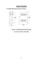
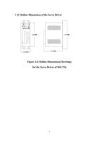
1.1 Outline Dimensions of the Servo Driver..................................................................................................3
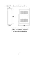
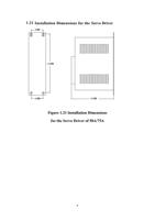
1.2 Installation Dimensions for the Servo Driver..................................................................................................4
1.3 Installation Site......................................................................................................................5
1.4 Direction and Space of Installation...........................................................................................................6
Chapter II Overview of Functions..........................................................................................................9
2.1 Basic Functions of DO-1000 Series of Servos.................................................................................9
2.2 Type Selection of the Servo Driver..........................................................................................................10
Chapter III Wiring..................................................................................................................13
3.1 Notices.....................................................................................................................13
3.2 Wiring Requirements.....................................................................................................................13
3.3 Wiring Methods.....................................................................................................................13
3.4 Typical Wiring....................................................................................................................14
3.4.1 Position Control (pulse type) ............................................................................................14
3.4.2 Speed Control (analog value) .............................................................................................15
3.4.3 Torque Control (analog value) .............................................................................................16
3.4.4 Wiring Diagram for Wire Saving Motor Encoder............................................................................................17
3.4.5 Wiring Diagram for the Band-type Brake of the Servo Motor.............................................................18
Chapter IV Interfaces..................................................................................................................19
4.1 Definitions of Servo Control Power Supply and Heavy Current Terminal........................................ 19
4.2 Definitions of CN1 Interface and Control Signal Input/output..................................................... 20
4.3 Definitions of CN2 interface and Encoder Input Signal.................................................................. 25
4.4 Principle of the Input Interface for Switching Value........................................................................................... 26
4.5 Principle of the Output Interface for Switching Value...............................................…....................... 26
4.6 Principle of the Input Interface for Pulse Value.................................................................................... 27
4.6.1 Input Mode of Pulse.......................................................................................................28
4.7 Principe of the input interface of Analog Value....................................................................................28
4.8 Principe of Encoder Interface..................................................................................................... 30
4.8.1 CN1 Output Interface for Encoder Signal (from the driver to the upper computer) ..................................... 30
4.8.2 CN2 Input Interface for Encoder Signal (from the servo motor to the driver) ................................................ 31
4.8.3 CN1 Output Interface for Z signal of the Encoder (from driver output to zeroing by the upper computer) ...31
Chapter V Display and Operation.......................................................... ...................................... 33
5.1 Operation Panel................................................................................................................. 33
5.2 Components of Parameter Structure...................................................................................................... 34
5.2.1 Status Monitoring Mode (DP- -)...................................................................................... 35
5.2.2 Parameter Modification Mode (PA--)............................................................................ ........... 38
5.2.3 Parameter Management Mode (EE--)....................................................................................... 39
5.2.4 JOG Operational Mode (Jr- -).............................................................................. ... 40
5.2.5 Speed Trial Run Mode (Sr- -).................................................................................... 40
5.2.6 Automatic Zeroing Mode of Analog Value (AU- -)........................................................................... 41
5.2.7 Automatic Zeroing Mode of Encoder (CO- -).......................................................................... 42
2

