FC300
Chapter 2 Installation and Connection
chassis instead.
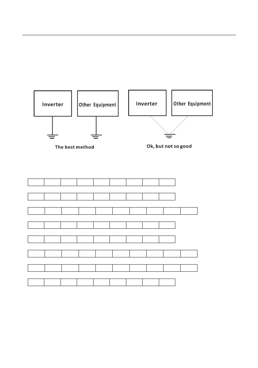
▲ It is recommended to adopt thick cable with demanded diameter no smaller then in the
attached form. Grounding wire should be near inverter, and ground wire be as short as
possible.
▲ When the motor is grounded on inverter side, please use one core of the four-core cable
to ground, with the same size to input wire.
2.4.4 Inverter Main Loop Terminal Row:
0.75KW-1.5KW, single phase 220V:
L N PE U V
2.2KW-3.7KW, single phase 220V:
W PB P+
LN
PB P+ U V W PE
5.5KW, single phase 220V:
LN
PB P+ P- U V W PE
0.75KW-2.2KW, three-phase 380V:
R S T PE U V W PB P+
3.0KW-5.5KW, three-phase 380V:
R S T PB P+ U V W PE
7.5KW, three-phase 380V:
P- P+ PB R S T U V W PE
11KW-15KW, three-phase 380V:
P- P+ PB R S T U V W PE
18.5KW, three-phase 380V:
R S T P+ P- U V W PE
Notes:
Different models may have some changes, please in kind prevail!
Inverter terminals (P+ , P-) shall be in accordance with braking unit terminal symbol during
wiring, damage will caused if wrongly connected.
The wire distance between braking unit and braking resistor unit shall be kept within 5
meters, or within 10 meters if using twisted pair.
13

