Chapter 2 Installation and Connection
FC300
Y2A、Y2B
Y1A、Y1B、Y1C
COM、12V
Relay contactor output
Relay contactor output
Auxiliary power supply
Y2A and Y2B are normally open contactors.
Y1A and Y1B are normally open contactors,Y1B and Y1C
are normally closed contactors.
COM, +24V≤50mA, COM are common position for analog
input/output and multi-function terminals.
2.4.3 Main Loop Connection
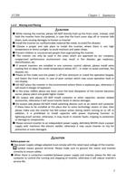
1. The crimping terminals for power supply or motors must be with insulation tube.
2. Keep in mind that NEVER connect power supply to output terminals of inverter (U, V, W),
otherwise it will damage inverter.
3. After wiring is finished, odd wires must be cleaned up, otherwise they may cause abnormal
performance, failure or fault. When boring on control stand, be aware to prevent the
fragments and powders from entering into inverter.
4. To keep the voltage drop within 2%, please use proper electric wires for wiring. When the
distance between inverter and motor is long, especially under the condition of low
frequency, motor torque will decline due to the decrease of main loop wire voltage.
5. Maximum line distance is 500m, especially for long-distance wiring. Because the parasitic
capacitor generates surge current, which may cause current protection, there will be the
abnormal performance and faults of the devices connected to output terminal. Therefore,
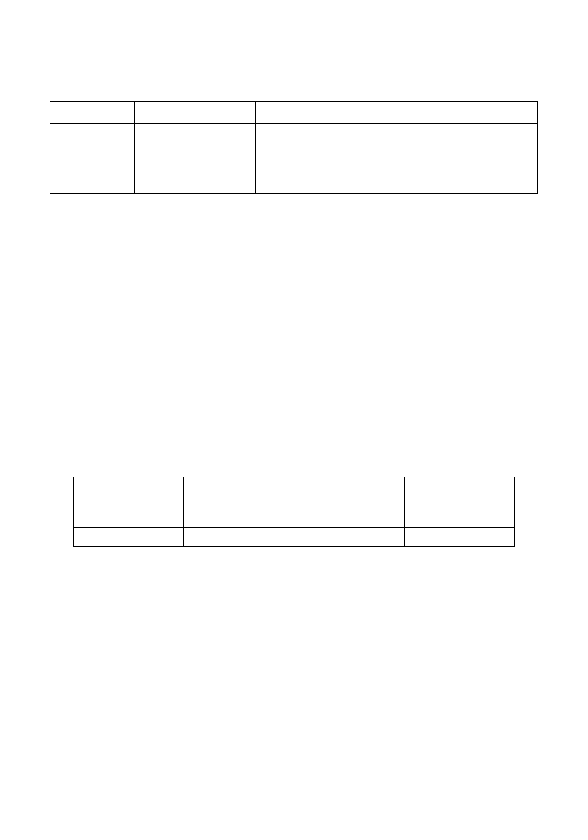
please refer to the maximum wiring distance as below (when inverter connects two or
more motors, wiring distance shall be within 500m):
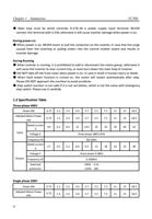
Inverter Capacity
Below 0.75KW
2.2KW
Above 4.0KW
Non-ultra-low noise
mode
100m
150m
200m
Ultra-low noise mode
50m
80m
100m
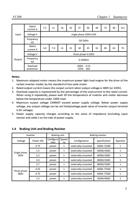
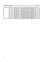
6. It is recommended to connect optional braking resistor between P+ and B- terminals.
7. Electromagnetic wave interference: there is harmonic wave in inverter input & output
circuits. In high-demanding circumstances please install wireless noise filter on input
terminal, to minimize the interference.
8. On inverter output terminal, DO NOT install power capacitor, surge suppressor or wireless
noise filter, which will lead to inverter fault or component damage.
9. When wiring change is required while power is on or inverter is running, inverter operation
must be stopped then wait for over 10 minutes after power is cut off. Check the voltage
by multi-meter then make the wiring change. There is still dangerous high voltage on
capacitor within a period after power is cut.
10. Ground terminal must be well grounded.
▲Since there is leakage current in inverter, in order to avoid electric shock, inverter and
motor must be grounded.
▲Use independent terminal for inverter grounding. DO NOT just use screw on shell or
12

