FC300
Chapter 2 Installation and Connection
installed together into one electrical control cabinet, please pay attention to select a proper
installation position, for ensuring the temperature surround the inverter is within the
permissible value. If the installation position is not correct, it will cause the surrounding
temperature to rise and the ventilation effect worse.
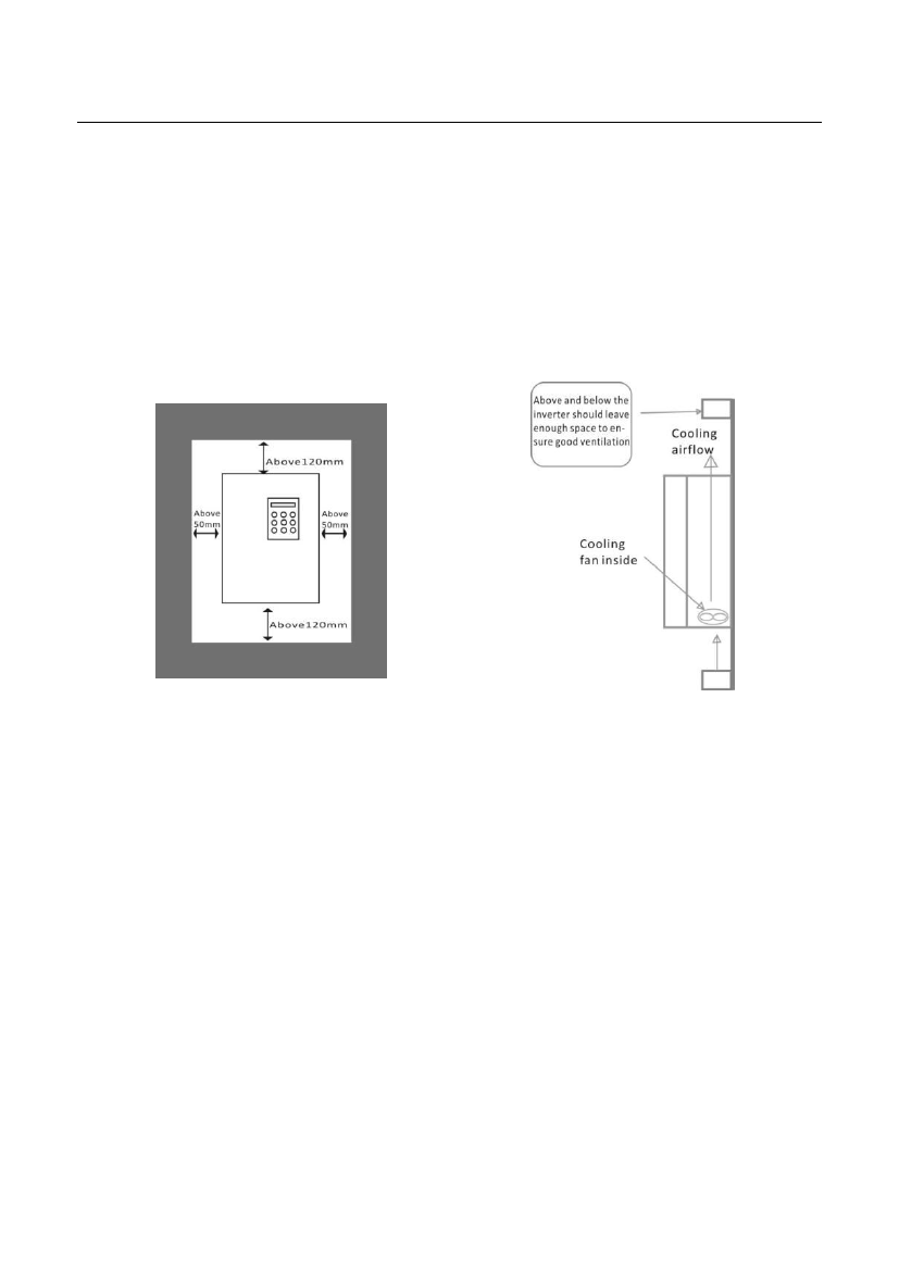
7. Please install inverter on a nonflammable surface. Inverter temperature may reach a rather
high value (about 80 °C). Meanwhile, in order to facilitate heat dissipation, please reserve
enough space around.
2.3 Connection Guidelines
1. Separate power supply line and control line while installing the wires, e.g. adopt
independent trunking. If control electrical circuit linking must across the cable, they should
be wired in 90°angle.
2. When using shield wire or twisted pair to connect control electric circuit, make sure the
unshielded part as short as possible, if conditions allow, please adopt cable sleeve.
3. Avoid the inverter gravity line(input and output line) and signal line to be parallel-wired or
clustered-wired but should be crossed-wired separately.
4. Please use twisted pair shield wire for connection line of detector and signal line for control.
The sheath of shield wire connects to COM terminal.
5. The ground wires of inverter and motor shall be connected on a common point.
6. Install data line filter onto signal line.
7. The shield layer of connector line of detector and control signal line must be grounded by
cable metal clamp.
9

